WEEK FOUR-FIVE:
Topic: Conversion of orthographic to isometric.
Content:
(i) Conversion of Orthographic to isometric.
Conversion of objects in orthographic projection to isometric
Method of conversion.
In converting an orthographic view to isometric, the following should be noted.
- The lowest point is the starting point.
- The height of the drawing is derived from the front view and not the plan..
- The width of the drawing is derived from the plan and end views and not the front view.
 Example 1

Method:
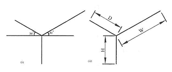
(i) Lay out the isometric axes.
(ii) Lay out the overall dimensions, blocking in the size of the object.
(iii) Draw the isometric box enclosing the object.
(iv) Locate other features by measuring along the isometric axes. ie all vertical lines should be drawn parallel to the vertical axis while all other lines should be drawn parallel to the receding axes.
(v) Remove layout lines and darken the remaining lines to complete the drawing.
 Example 2

Method:
(i) Draw a horizontal line of any convenient length and mark a point G (lowest point) on it.
(ii) From point G, draw a receding line GZ to the right and GX to the left at angle 300 to the horizontal.
(iii)Mark-off lengths G-z and G-x on both receding lines respectively.
(iv)Draw a vertical line z-5 representing the overall height and complete the rectangular box in isometric.
(v)Mark the offsets 5-4, 6-2, G-3 and X-1 on the rectangular block.
(vi)Join 1-3, 2-4, 1-2 and 3-4.
(vii)Use thick continuous line to bring out the shape and clean off unnecessary construction lines.
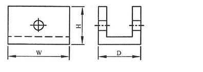
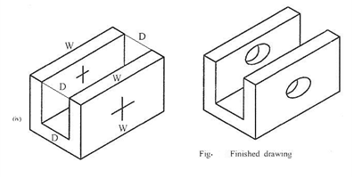
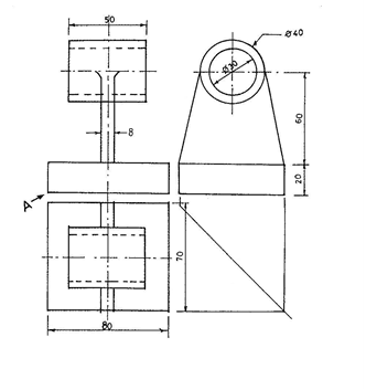
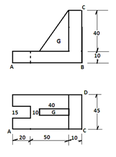 Example 3. Convert the orthographic drawing shown below to isometric.
Method:
- Draw a horizontal line of a convenient length and mark the lowest point on it.

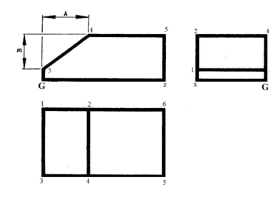
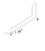
 Choose point A as the lowest point and draw a line from A at an angle of 300 to the horizontal to point B as seen in the given elevation. If B were to be the lowest point, a line would go from point B to the left. See the diagrams below.
 Choose point A as the lowest point and draw a line from A at an angle of 300 to the horizontal to point B as seen in the given elevation. If B were to be the lowest point, a line would go from point B to the left. See the diagrams below.
- Ensure that all receding lines to the left and right are parallel to each other. The same is applicable to all vertical lines..
- Mark off your dimensions to obtain the isometric drawing.
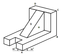
 Make use of all the given views in order to have a good picture of what is needed. For instance, the part labeled G appears to be at the edge of the front view. But the plan shows it to be at the middle.
 Make use of all the given views in order to have a good picture of what is needed. For instance, the part labeled G appears to be at the edge of the front view. But the plan shows it to be at the middle.
Evaluation questions
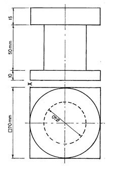 1. The figure below shows two views of a Mechanical component in 1ST angle projection. Draw it full size in isometric projection making X the lowest point.
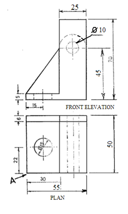
- The figure below shows three views of an engineering component in 1st angle orthographic projection. Draw it full size in isometric. Make point A the lowest.
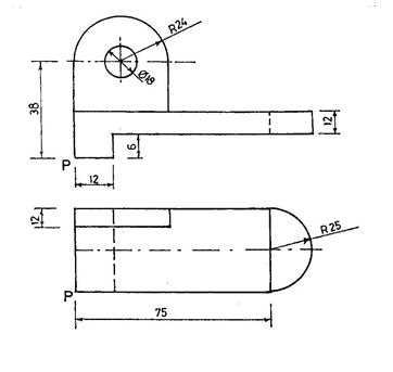 3. The figure below is two views of a mechanical component shown in 1ST angle projection. Draw it full size in isometric projection . Make P the lowest point.
4. The Figure below shows three views of an engineering block in first angle orthographic projection.
Draw the diagram in isometric. Make A the lowest point.

Reading assignment
Technical drawing by JN Green pages 160 – 171and 184 – 187
Weekend Assignment
Objectives
- The axes of isometric drawing are spaced at an angle of A. 900 B. 1800 C. 1200 D. 1350
- The receding lines of an isometric drawing are drawn at what angle to the horizontal? A. 900 B. 1800 C. 1200 D. 300
- Which of the following orthographic views is used to determine the height of an isometric drawing? A. Plan. B. Front. C. End D. None of the above.
- Which of the following orthographic views is used to determine the width of an isometric drawing? A. Plan. B. Front. C. Section D. None of the above.
- The point from where an isometric drawing is started is called A. highest point.
B. middle point. C. lowest point. D. center point.
Theory
 1. The figure below shows two views of a Mechanical component in 1ST angle projection. Draw it full
size in isometric projection making P the lowest point.
 2. The figure below shows two views of an engineering component. Draw it full size in isometric
projection making A the lowest point.