THIRD TERM E-LEARNING NOTE
SUBJECT:TECHNICAL DRAWING CLASS: SS2
THIRD TERM SCHEME OF WORK
WEEK 1& 2: Revision on building details; Simple working drawing and details.
WEEK 3 & 4: Construction details of parts of building e.g foundation, wall openings, jamb, sill, lintel.
WEEK 5 & 6: Construction details e.g roofs, doors, windows, staircases, frames, lining and architraves, floors,
simple reinforcement for columns, beams, piers and slabs.
WEEK 7 & 8: Orthographic projection of building, including sectional views and the use of different scales up tofloors only.
WEEK 9: Revision of construction details and orthographic projection.
WEEK 10 & 11: Engineering Drawing- free-hand sketching including both pictorial and orthographic sketching of
engineering components.
WEEK 12 & 13 Revision and Examination.
REFERENCE MATERIALS:
Technical drawing by J.N. Green
Drafting Technology and practice by William P. Spence.
Technical drawing manual with solved past questions by E.K Ajayi.
WEEK ONE
TOPIC: REVISION ON BUILDING DRAWINGS DETAILS
CONTENT:
(i) Definition of terms
(ii) Details of working drawing.
Definition of terms
Foundation: Foundation sometimes called footing or the sub-structure is designed to support the walls and the roof and to provide a solid base on which to build a house. It helps in the evenly distribution and conduction of the entire building load on the soil in a manner that no damaging settlements take place.
Plinth: A plinth is normally constructed above the ground level and immediately after the foundation.
Damp proof course(Dpc): This is a layer of water proof material which prevents surface water from risinginto the walls.
Floors: This is the surface above the filling of the plinth beam on which we most of our activities.
Walls: This is the vertical member on which the roof structure rest.
Openings: Openings are made on walls to serve the purposes of ventilation, reflection of day light into theinteriors of a building and for beauty. Examples of openings include: windows, doors, arches, manholes etc.
Meaning of working drawing
Working drawing is a type of architectural or mechanical drawing from which construction work is actually carried out. Therefore, they must give all the graphical information necessary for constructional purposes and must be accurately drawn in orthographic projection showing the plan, elevations and essential sections. There are working drawings for mechanical components, site plan, foundation plan, floor plan and elevations. They must have detailed dimensioning, appropriate titles and the scale used.
EVALUATION
1. Define a working drawing.
2. Mention some of the features of a working drawing.
Examples of working drawing
Building drawing


Mechanical drawing
EVALUATIONs
1. Draw a floor plan of your dream bungalow building.
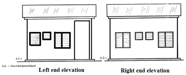
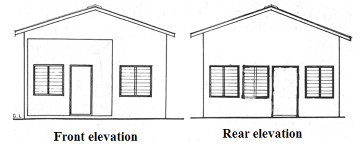
2. Sketch the front, end and rear elevations of your school building.
READING ASSIGNMENT
Visit www.google.com for types of working drawings.
Drafting technology by Spence pages 687 – 704.
WEEKEND ASSIGNMENT
Objective
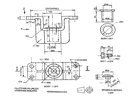
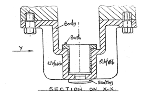
 1. Which of the following parts is not a member of the assembly whose two views are shown below? A. Bolt.
B. Web. C. Washer. D. Lever.
2. On a working drawing of a bolt. Which of the following is the correct interpretation of
‘ BOLT- 4 off ‘? A. Bolt is number 4 on the bolts chart. B. 4 bolts required for the assembly. C. Bolt
should have an off-cut of 4mm. D. 4 machines are required to produce the bolt.
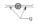 3. On a building floor plan, the symbol above represents A. window. B. lintel. C. door. D. column.
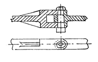
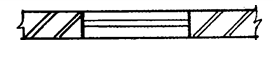
4. On a mechanical drawing shown above, Q can be identified as A. wood. B. web .C. joint. D. groove
 5. In a building floor plan. the part shown below can be identified as a A. lintel B. door. C. window.
D. Arch
Theory
1. Mention 5 characteristics of a working drawing.
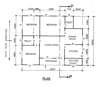 2. The figure below shows the sketch plan of a three bedroom bungalow. Study the given specifications and
answer the following questions.
SPECIFICTIONS
Foundation: 800 X 225 strip laid 1000 below ground level.
Wall: All walls are 225 thick sandcrete, hollow blocks, with 13 mortar rendering on both sides.
Floor: 300 hardcore; 150 thick concrete slab; 25 mortar screed.
Finished floor to ceiling, 3000.
Doors: Main entrance – 2100 X 1800 flush wooden in 120 X 80 timber frame.
Inside – 900 X 210 X 40 flush wooden in 100 X 50 timber frame.
Kitchen (outside) – 900 X 2100 fabricated metal in 100 X 50 metal frame’
Windows: All glass louvred with aluminum carriers in 100 X 50 timber frames.
Toilets (W1) – 800 X 500.
Others – 1400 X 1200.
Lintel: 225 X 255 reinforced concrete.
Roof: Pitch angle 120 (gable roof) with corrugated aluminum sheets; 300 eaves projection; timber
rafter 200 X 50 at 1000 centres; purlins 75 X 50 at 900 centres; ceiling joist 50 X 50 at 1200
centres.
Note: (Assume suitable dimensions where necessary)
Draw the:
(a) floor plan of the building to a scale of 1 : 100;
(b) front elevation of the building to a scale of 1 : 100;
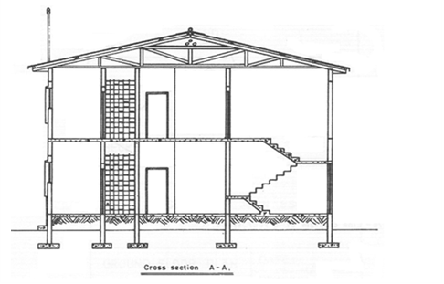
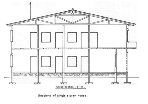
(c) sectional elevation P – P of the building to a scale of 1 : 50.