WEEK SEVEN
Topic: Blue print
Content:
(i) Meaning of blue print.
(iii) How to read blue print.
Meaning of blue print
 Blueprints are 2-dimensional architectural design drawings that indicate the size of a planned building, the materials to be used in its construction, and the placement of its features. Architects and Engineers use blueprints and written specifications to communicate necessary details with construction workers. Learning to read blueprints is essential not only for construction workers but also for the people who hire architects to draft blueprints, so that they can make more informed decisions on construction and renovation projects.
Evaluation questions
- Define blue print.
- State the importance of blue print in consruction.
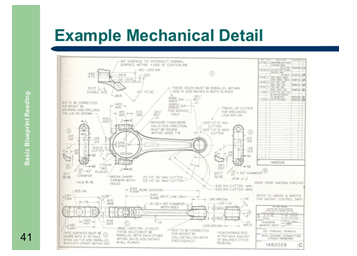
How to read blue print
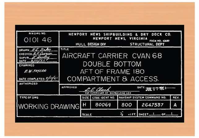
- Read the title block.
These often appear at the beginning of any blueprints. If you are involved in any serious construction work, you will want to make sure to read it all thoroughly.
- The title block’s first section lists the blueprint’s name, number, as well as the location, site, or vendor.[ If the drawing is part of a series this information will also be listed. This section is largely for filing and organizational purposes.
- The second section comprises bureaucratic information. Approval dates and signatures are located here. If you find a blueprint that interests you and want to know more, this information can be invaluable.
 Section three of the title block is the list of references. This lists all other drawings that are related to the building/system/component, as well as all blueprints that were used as reference/inspiration. Similar to the second section this can be incredibly helpful if you are to begin your own blueprint.
 Section three of the title block is the list of references. This lists all other drawings that are related to the building/system/component, as well as all blueprints that were used as reference/inspiration. Similar to the second section this can be incredibly helpful if you are to begin your own blueprint.
- Read the revision block.
 Any time changes to a building/system/component are made, the drawing has to be redrafted. Those changes are listed here.
 Any time changes to a building/system/component are made, the drawing has to be redrafted. Those changes are listed here.
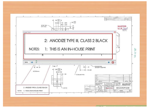
- Read the notes and legend.
In addition to the standard scale, grid, and lines, blueprints are often comprised of other symbols and numbers. In order to fully comprehend the specific blueprint you’re working with, be sure to learn those symbols by reading through the legend. The notes will reveal any specifications or information the designer thinks will aid in understanding the drawing.
- For projects that actually begin construction it is even more important to read the notes. It’s possible practical information like, “Do not begin working until 8am,” will be listed.
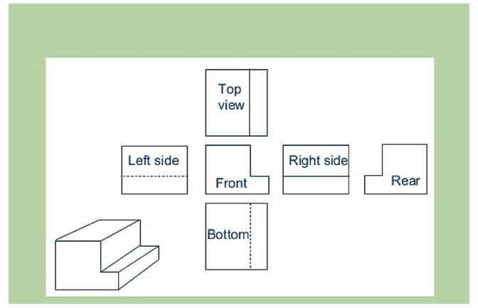
- Determine the view.
With 2D blueprints, there are three common perspectives: plan, elevation, and section.[2] Understanding which one of these is being employed is an important first step to reading any drawing.
- Plan: A bird’s eye view of planned work. Usually this is done on a horizontal plane at 30″ above the floor. This perspective allows precise mapping of width and length.
- Elevation: A view of planned work from the side. These drawings are usually oriented from the north, east, west, or south. Composing an elevation map allows for detailed planning of height dimensions.
- Section: A view of something as if it were cut through. This perspective is generally imaginary, and is used to show the inner workings of how something will be built.

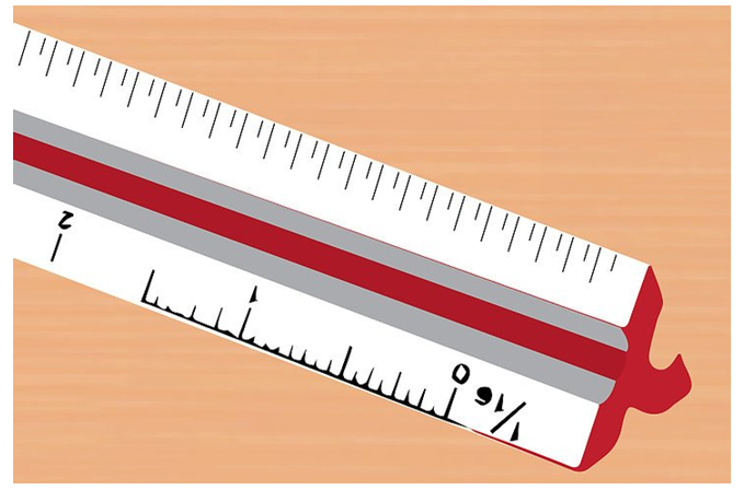
- Establish the scale in your mind.
Blueprints are scaled down representations of things like houses, underground piping, and power line. To ensure proper construction, always use precise measurements. The scale sets a rule for the entire drawing, saying what measurements on the drawing are equal to in real life. For example 1/8″ = 1′ (one eighth inch equals one foot).
- Architectural scales are used for the construction of building exterior and interiors; for establishing doors, windows, and walls. Many are presented in fractions: 1/4″ = 1′ (one-fourth inch equals one foot), 1/8″ = 1′ (one-eighth inch equals 1 foot). [3]
- Engineer scales, or civil scales, are used for public water systems, roads and highways, as well as topographical endeavors. They use whole-integer ratios like 1″ = 10′ (one inch equals 10 feet) or 1″ = 50′ (one inch equals fifty feet).
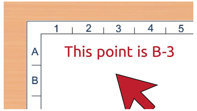
- Inspect the grid system.
Along the horizontal and vertical edges of a blueprint, drawers often fix a simple grid system with numbers on one axis and letters on the other. This allows anyone reading the plans to reference the location of a point or object within the drawing. For example,
If you are looking over the drawings with a team or partner and can’t physically point to the location
you’re discussing, grid systems are very useful. This could be the case if you working online from
different locations, or the other person/people simply isn’t in the room with you.
- Locate any doors and windows.
 On blueprints, doors look like larger gaps between walls. There will also be a curved line with a mock door extended in or out of the door frame. This reveals which way the door will swing upon construction. Windows are likewise identified by the end of object lines and will typically be represented realistically to show their size.
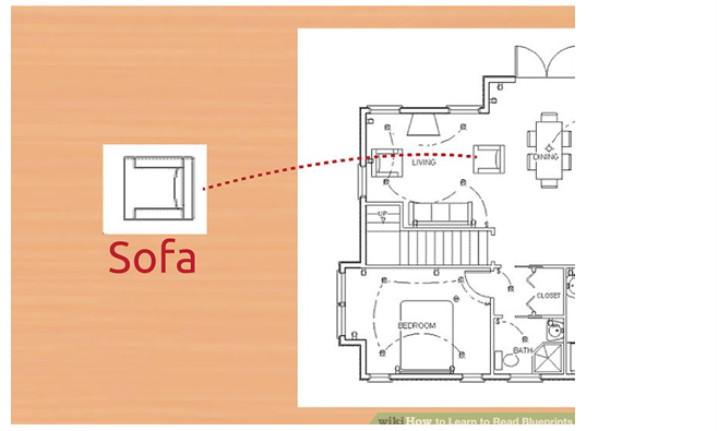
- Identify any appliances.
Fridges, toilets, sinks, ovens, stove-tops burners, and the like will be represented by simplistic representations that are readily recognizable. Take the time to consider whether they are located in an area where you want them. Although it may seem like their placement comes second the establishing walls, they can end up playing a more important role in deciding on design specifications.
Evaluation questions
State five areas to be focused on while reading blue print.