WEEK TWO
TOPIC: ALTERNATING CURRENT (II)
CONTENT
- A.C in Resistor, inductor and capacitor
- Energy in inductance, Reactance and impedance
- Vector Diagram
- Power in A/C
- Resonance and its applications
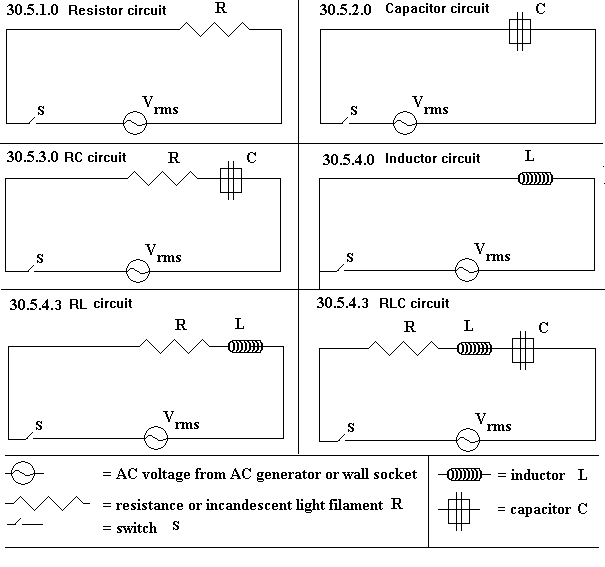
At any instant, the current through the resistor R, is I an the voltage across it is V
From ohm’s law, V = IR
Thus the current is given by I = V
R.
But V = Vo sin wt
I = V
= Vo sin wt
R R
I = Io sin wt
The voltmeter and ammeter connected in the circuit will read the r.m.s values of voltage and current
I r.m.s. = Vr.m.s
R. …………………………………………………………………..4
The voltage and the current are said to be in phase or in step with each other . This means that both of them attain their maximum, zero and minimum values at the same instant in time.
Capacitance in an a.c circuit
In the circuit above, an a.c. voltage is connected in series with a capacitor.
![]()
![]()
![]() IC
IC
π/2 rad
VC
Ic leads Vc by π radians or 90o or by ¼ cycle
2
The voltage (v) and current ( I ) are out of place ( not in step) . the current is said to lead on the voltage and the voltage is said to lad on the current. The phase difference between the current and the voltage is 90o or ( π/2) radian
V = Vosinwt
I = Io sin (wt + π/2)
The capacitor opposes the flow of current. This opposition to the flow of a.c. offered by the capacitor is known as capacitive reactance, Xc. This is given by the relation
Xc = 1
2πfC ………………………………………………..5
when an a.c.. voltage of frequency f is applied to a capacitance, c, then
V = IXc …………………………………………………………………………… 6
In other words, from ohm’s law relation, when applied to a capacitor.
In it, R is replaced by:
Xc = 1 . Hence the unit of Xc is in ohms
2πfC
Example
A 2µF capacitor is connected directly across a 150Vrms, 60Hz a.c source. Find
a) the r.m.s value of the current
b) the peak value of current.
Xc = 1 .
2πfC
= 1
![]() 2π x 60 x ( 2 x 10⁻⁶)Ώ
2π x 60 x ( 2 x 10⁻⁶)Ώ
= 1324.4 Ώ
From V = IXc
I r.m.s. = Vrms = 150 .
Xc 1324.4
= 0.113A.
Peak current, Io = √2 Ir.m.s. = 0.160A
EVALUATION
Determine the r.m.s. value of the current in an a.c circuit with a 5.5µF capacitor across a 220Vr.m.s, 50Hz.
Inductance in A.C Circuit
VL leads IL by π/2 radians or 90o. The induced e.m.f. in the inductor L opposes the change in the current.As a result the current is delayed behing the voltage in the circuit. The current lads behind V by π/2 radian or 90o or by ¼ cycle. I and V have a phase difference of 90o (π/2)
![]()
![]()
![]() π/2 rad VL
π/2 rad VL
IL
V = Vo sin wt
I = Io sin (wt – π/2 ).
Like R and C, an inductor L opposed the flow of current; i.e it has an impedance effect known as inductive reactance, XL.
V = I X L …………………………………………………………………………………… 7
The unit of XL is in ohms
XL = 2πfL ………………………………………………….. 8
The unit of L is Henry (H), f is in hertz (Hz) and XL is in ohms.
Reactance is the opposition to the flow of a.c offered by a capacitor or an inductor or both.
Find the impedance across an inductor of 0.2H inductance when an a.c voltage of 60Hz is applied across it, if the voltage is given by V = 150 sin 120πt. Calculate the r.m.s and peak values of the current.
XL = 2 πfL = 2π x 60 XL = 120πL = 120 x π x 0.2 = 75.40Ώ
V= 150 sin 120 π t
Vo = 150V F = 60Hz
Vrms = 0.76 = 0.7 x 150 = 105V
Irms = Vrms = 105
XL 75.4
= 1.39A
Io = Vo = 150
XL 75.4
= 1.99A
EVALUATION
Determine the r.m.s. value of the current in an a.c circuit with a 5H capacitor across a 220Vr.m.s, 50Hz.
Series Circuit Containing Resistance (R)Inductance (L) and Capacitance (C)
If an alternating voltage V = Vo sing 2πft is put across the circuit, it is observed that a steady state current given by I = Iosin2πft will flow along the circuit . The maximum or peak value of the current is given by
![]() Io = Vo
Io = Vo
√ (R2 + (XL – Xc)2 ) …………………………………………………………………….. 9
![]() = Vo
= Vo
√R2 + X2
X= XL -XC.
Let Z =√ ( R2 + (XL –XC )2 )
:. Io = Vo
Z
Ir.m.s. = Vr.m.s
Z
Z is known as the impedance of the circuit.
Impedance (Z) is the overall opposition of a mixed circuit containing a resistor, an inductor and or a capacitor. It is measured in ohms.
![]() Xc = 1
Xc = 1
WC
= 1
![]() 2πfC
2πfC
XL = WL = 2πfL
= Z = √R2 + ( wL – 1 )2 )
wc
Z = √R2 + ( 2πfL – 1 )2
2πfC
in summary
V= IR
VL = I X L
Vc = I X C
V = IZ
V= I √(R2 + (XL – Xc)2 )………………………………………………………………… 10
Example
(1) Find the r.m.s. value of an alternating current whose peak value is 5A.
Irms = Io
√2
= 0.707Io = 0.707 X 5 = 3.53A.
(2) in a.c circuit the peak value of the potential difference is 180v. What is the instantaneous p.d when it has reached 1/8th of a cycle/
1 cycle = 360o
1/8 of a cycle = 360/8 = 45o
E = Eo sin wt = Eo sin 45
= 180sin 45
= 180/√2
= 90√2V.
3. A circuit consist of a resistor 500 ohms and a capacitor 5uF connected in series . if an alternating voltage of 10v and frequency 50Hz is applied across the series circuit. Calculate:
i. the reactance of the capacitor
ii. the current flowing in the circuit
iii. the voltage across the capacitor
(b) If the capacitor is replaced with an inductor of 150mH, calculate the impedance and voltage across the inductor.
Xc = 1
2πfc
![]() = 1
= 1
2π x 50 x 5 x 10-6
= 636.62 ohms
II. Z = √R2 + Xc2
= √5002 + 636.622
= 809.5 Ω
I = V = 10 .
Z 809.5
= 12.35 x 10⁻³ A
12.35 mA.
iii. Vc =I X c = 12.35 x 10-3 x 636.62 = 7.86 V
(b)XL = WL = 2π x 50 x 150 x 10-3 = 47.12 Ω
Z = √ R2 +XL
2 = √5002 – (47.12)2 = 497.7 Ω
I = 10 .
497.7
= 0.02A
VL = 1 x L = 0.02 x 47.12
= 942.4mA.
EVALUATION
An a.c circuit consist of a resistor 100Ω, an inductor 20H and a capacitor 5.0µF connected in series. If the source has 220Vr.m.s, 50Hz across it, calculate; (i). the impedance, (ii). the current flowing in the circuit.
VECTOR DIAGRAM
When an alternating voltage is placed across a R.L.C series circuit, the resulting alternating current I. has the same frequency as the voltage (v0 but the two differing phase or are said to be out of phase.
Phase is the state of vibration of a periodically varying sytems at a particular time, wt = phase angle
Two vibrating systems with the same frequency are said to be inphase if their maximum, minimum and zero values occur at the same time; otherwise they re said to be out of phase.
The phase difference between the voltage and the current through an RLC series circuit is given by
Tan θ = X
R
X = reactance =XL – Xc and R is the resistance .
For a circuit containing only a resistance R, the a.c voltage vibrates in phase or in step with the alternating current.
Thus Ǿ = O
For a circuit containing only a capacitance C, Vc and Ic are out phase by 90⁰ or (π/2) radian. This means that the angle by which a particular phase Ic is in advance of a similar phase of Vc is 90⁰ or π/2 radian or ¼ cycle
If Vc = Vo sin wt
Then Ic = Io sin (wt – π/2).
iii. If only an inductor L is connected to the a.c voltage, the current IL, lags on the voltage vL by π2 radians
VL = Vo sin wt
IL = Io sin (wt – π/2)
![]() In a circuit containing RLC the current is the same for all the components of the circuit, and is in phase with the voltage across R. let VR be the reference vector, the other voltage vectors acts as shown
In a circuit containing RLC the current is the same for all the components of the circuit, and is in phase with the voltage across R. let VR be the reference vector, the other voltage vectors acts as shown
![]() VL– VC
VL– VC
VL XL– XC
XL
![]()
![]()
![]()
![]() VR
VR
R VR
R
VC XC
The effective voltage V is given by
V2 = V2R + (VL – VC)2 …………………………………………………………………….. 11
Tan Ǿ = VL – VC
VR
= XL – XC
R.
If XL > XC, Ǿ is positive and I lags.
If XL < Xc,Ǿ is negative and I leads V
For R and L series, we have
V2 = V2R + V2L.
I = V .
√R2 + X2L
Z = √R2 + X2L
Current I, lags on the applied voltage by Ǿ given by
Tan Ǿ = VL
VR
= XL
R
![]()
![]()
![]() V
V
I
I lags V or V leads I
For R and C in series
V2 = V2R + V2C
I = V
√R2 + X c2
Z = √R2 + Xc2
Tan Ǿ = Vc = Xc
VR R
V lags I or I leads V.
POWER IN AN A.C CIRCUIT
The average power in an a.c circuit is given by;
P = IV cos Ǿ
I, V are the effective (r.m.s) values of the current and voltage respectively and Ǿ is the angle of lag or lead between them . The quantity cos Ǿ is known as the power factor of the device. The power factor can have any value between zero and unity for Ǿ varying from 90o to 0o. For Ǿ = 90o or cos Ǿ = 0, average power P is zero. A power factor of zero means the device is either a pure reactance, inductance or capacitance. Thus no power is dissipated in an inductance or capacitance.
However, if I is the r.m.s value of the current in a circuit containing a resistance R, the power absorbed in the reactance is given by
P = I2R …………………………………………………………… 12
For an a.c circuit, the instantaneous power is given by
P =IV (instantaneous value)
Power factor
Cos Ǿ = Resistance
Impedance …………………………………………………………. 13
Example
A series circuit consist of a resistance 600 ohms and an inductance 5 henry’s .An a.c voltage of 15v(rms) and frequency 50hz is applied across the circuit, calculate
i the current flowing through the circuit
ii. the voltage across the inductor
iii. the phase angle between I and the applied voltage
iv. the average power supplied
v. the p.d across the resistance.
XL = 2πfl = 2 πx 50 x 5 = 500πohms
Z = √R=Xl = √(600)2 + (500π)
= 1.69 X 10 3 Ω
Ir.m.s = Vrms = 15 = 8.88 x 10⁻³ A = 8.88mA
Z 1.69 x 10³
ii. voltage across the inductor
VL = I XL = 8.88 x 10-3 x 500 π = 4.44πvolts = 14.95 volts
iii. tan Ǿ = XL = 500π = 2.62.
R 600
Ǿ = tan-1 ( 2.62) = 69.10
iv. Power supplied
P = I2R
= (8.88 x 10⁻³)2 x600
= 4.73 x 10⁻² w
v.p,d across R.
V =IR
= 8.88 x 10-3 x 600
= 5.53ohms.
EVALUATION
- An a.c circuit consist of a resistor 100Ω, an inductor 20H and a capacitor 5.0µF connected in series. If the source has 220Vr.m.s, 50Hz across it, calculate the; (i) voltage across the inductor, (ii) voltage across the capacitor.
- In the circuit in (1) above, determine the; (a)average power in the circuit, (b) power developed in (i)the inductor, and (ii)the capacitor.
RESONANCE IN RLC
Series Circuit
The current in RLC series circuit is given by:
I = V = V .
Z √R2 + (XL – Xc )2
The maximum current is obtained in the circuit when the impedance is minimum. This happens when XL = Xc
2πfL = 1 .
2πfC
Resonance is said to occur in an a.c series circuit when the maximum current is obtained from such a circuit. The frequency at which this resonance occur is called the resonance frequency (fo). this is the frequency at which XL = Xc
2πfoL = 1 .
2πfoC
4π2fo2LC = 1
fo2 = 1 .
4π2LC
fo = 1
2π √LC …………………………………………………………… 14
since w = 2πf
wo = 1 .
√LC
NOTE: At f = fo, the current is maximum.
APPLICATION OF RESONANCE
It is used to tune radios and tvs. Its great advantage is hat it responds strongly to one particular frequency.
Examples
An a.c voltage of amplitude 2.0 volts is connected to an RlC series circuit. If the resistance in the circuit is 5 ohms, and the inductance and capacitance are 3mh and 0.05 uf respectively. Calculate:
- the resonance frequency,fo
- the maximum a.c. current at resonance.
Fo = 1 .
2π√LC
= 1 .
2π√3 x 10-3 x 0.05 x 10-6
= 1 .
2π√3 x 10-11
= 1299. 545Hz
1.3KHz
At resonance X = R since XL =XC
I = Vo
R
= 2
5
= 0.4A
READING ASSIGNMENT
New School physics pag 458-463
GENERAL EVALUATION
- Why is water not used as a thermometric substance.
- Differentiate between evaporation and boiling.
WEEKEND ASSIGNMENT
- A voltage supply of 12V r.m.s anf frequency of 90Hz is connected to a 4Ω resistor. Calculate the
peak value of the current . (a) 48.8A (b) 30.0A (c) 27.5A (d)4.2A
- A 2µF capacitor is in series with a resistor of 5000Ω. A voltage of 5V r.m.s and frequency, I= 100Hzis connected to them. What is the capacitive reactance?
- 795.5Ω (b) 895.5 Ω (c)1795Ω (d) 2005.0Ω
3. At what frequency will 20uf capacitor have a reactance of 500 ohms?
(a) 100Hz (b) 50Hz (c) 150Hz (d) 100π Hz (e) 30Hz
π π π π π
4. In an RLC series a,c circuit power is dissipated in (a) Resistance only (b) Reactance only (c) Resistance and reactance (d) Resistance, inductance and capacitance
5. In a series L-C circuit, the inductance and the capacitance are 0.5H and 20µF respectively. Calculate the resonance frequency of the circuit (a) 24.2Hz (b) 36.7Hz (c) 50.3Hz (d) 60.5Hz
THEORY
- Explain what is meant by the terms impedance, phase angle and reactance as applied to an a.c. circuit. Calculate the impedance and phase angle for an a.c. circuit having a 100ohms resistance, 5uf capacitor in series if an a.c voltage of frequency 100Hz is applied across the circuit.
- Draw a vector diagram of the relationship of I and V for an a.c. circuit containing
(a) a pure inductor (b) a pure capacitor (c ) a pure resistor