SECOND TERM E-LEARNING NOTE
SUBJECT: TECHNICAL DRAWING CLASS: SS 3
SCHEME OF WORK
WEEK TOPIC
1 Revision of past work.
2 Introduction to computer- parts, simple practical exercise on AutoCAD for building and mechanical drawing.
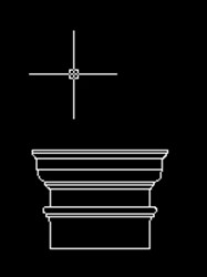
3 Architraves- semi-circular, lancet, segmental, t.udor, parabolic, elliptical, flat guage etc.
4 Architraves continued.
5 Roofs: types and structure including the plan /determination of pitch angle.
6 Conventional representation of materials and symbols.
7 Blue print.
8 Revision.
WEEK ONE Revision of past work
![]()
CONTENT
(i) General revision of past work
WEEK TWO
Introduction to computer and simple exercises on AutoCAD
CONTENT
(i) Meaning and uses of a computer
(ii) Parts of a computer.
(iii) Component of a computer.
MEANING AND USES OF A COMPUTER
A computer is a machine that can respond to instructions and perform a list of instructions. It can store, retrieve and process data. It can be programmed with a set of instructions.
A computer can be used to type documents, send e-mail, browse the internet, handleaccounts (spreadsheet), create presentations, manage database, play games, draw graphics, just to mention just a few.
PARTS OF A COMPUTER
A normal desktop PC comes with the following parts or units.
- Monitor
- Central processing unit(Cpu)
- Keyboard
- Mouse
- Speakers
COMPONENTS OF A COMPUTER SYSTEM
A personal computer system consists of four main components. These include
- Hardware
- Software
- Data
- Users
EVALUATION QUESTIONS
- What is a computer?
- State five parts of a computer.
- State four components of a computer.
AutoCAD is a drawing package used for graphic constructions and designs.
There are two types of tool used in AutoCAD. These include draw tools and modify tools.
DRAW TOOLS

The line command


![]() With the Line command you can draw a simple line from one point to another. You can also draw lines by entering the co-ordinates of their end points at the command prompt rather than picking their position from the screen. This enables you to draw lines that are off screen, should you want to.
With the Line command you can draw a simple line from one point to another. You can also draw lines by entering the co-ordinates of their end points at the command prompt rather than picking their position from the screen. This enables you to draw lines that are off screen, should you want to.
- The construction line command
The Construction Line command creates a line of infinite length which passes through two picked points. Construction lines are very useful for creating construction frameworks or grids within which to design.

- The Ray command
The Ray command creates a line similar to a construction line except that it extends infinitely in only one direction from the first pick point. The direction of the Ray is determined by the position of the second pick point.
 The polyline command
 The polyline command
The Polyline or Pline command is similar to the line command except that the resulting object may be composed of a number of segments which form a single object.
The Polyline Family
Polylines differ from lines in that they are more complex objects. A single polyline can be composed of a number of straight-line or arc segments. Polylines can also be given line widths to make them appear solid.
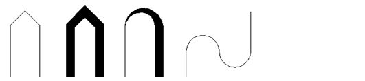 The illustration below shows a number of polylines to give you an idea of the flexibility of this type of line.


5. The rectangle command
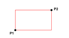 The Rectangle command is used to draw a rectangle whose sides are vertical and horizontal. The position and size of the rectangle are defined by picking two diagonal corners. The rectangle isn’t really an AutoCAD object at all. It is, in fact, just a closed polyline which is automatically drawn for you.

6. The polygon command
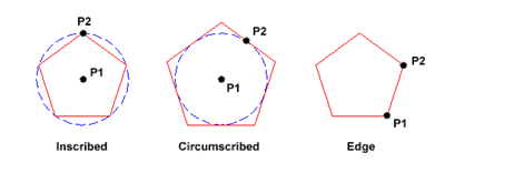 The Polygon command can be used to draw any regular polygon from 3 sides up to 1024 sides. This command requires four inputs from the user, the number of sides, a pick point for the centre of the polygon, whether you want the polygon inscribed or circumscribed and then a pick point which determines both the radius of thisimaginary circle and the orientation of the polygon. The polygon command creates a closed polyline in the shape of the required polygon.
![]()
7. The donut command
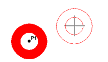 The donut command is used to draw shapes in the form of a donut. They are constructed from single closed polylines composed of two arc esgments which have been given width.
![]()
8. The revcloud command
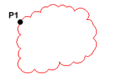 The Revcloud command is used to draw a “freehand” revision cloud or to convert any closed shape into a revision cloud.Move the mouse to form a closed shape; the command automatically ends when a closed shape is formed.
 9. The circle command
 The Circle command is used to draw circles. There are a number of ways you can define the circle. The default method is to pick the centre point and then to either pick a second point on the circumference of the circle or enter the circle radius at the keyboard.

 10. The arc command
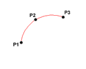 The Arc command allows you to draw an arc of a circle. There are numerous ways to define an arc, the default method uses three pick points, a start point, a second point and an end point.

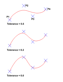
11. The spline command
The Spline command creates a type of spline known as a non-uniform rational B-spline (NURBS)
A spline is a smooth curve that is fitted along a number of control points.
 12. The ellipse command
 The Ellipse command gives you a number of different creation options. The default option is to pick the two end points of an axis and then a third point to define the eccentricity of the ellipse. The ellipse command can also be used to draw isometric circles.
13. The multilinecommand
 The Multiline command is used to draw multilines. This process of drawing is pretty much the same as drawing polylines, additional line segments are added to the multiline as points are picked. As with polylines, points can be unpicked with the Undo option and multilines can be closed.
Evaluation Questions
- State six types of AutoCAD draw tools.
- Differentiate between the line command and the polyline command.
MODIFY TOOLS
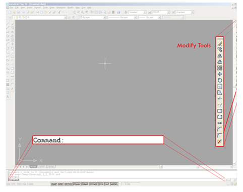 While working with AutoCAD, you’ll quickly run into situations that require you to use modify tools. As the name suggests, modify tools are used to modify existing lines and objects. AutoCAD has a whole range of modify tools.

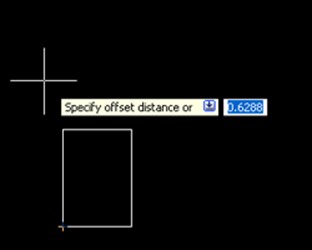
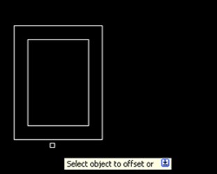
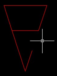
The offset command

The offset command is used to create a duplicate object parallel with the original object. If this object is a Polyline or a Circle, the duplicate shape will be transformed inwards or outwards. This option can be useful to make closed steel profiles.
To offset: First select the offset distance; [enter]; select the original object; specify on which side you want to offset.


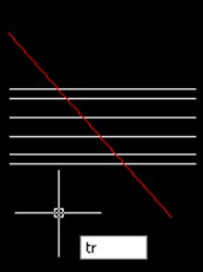
The trim command
With the trim option objects can be shortened or lengthened with the edges of other objects. Objects can exactly be fitted between these objects.
To trim an object: Type tr in the command line; optionally select the line(s) you want to trim (otherwise all objects are used, which is fine in most cases); [enter]; select the objects to trim.
To trim multiple objects at once you can drag a selection window.
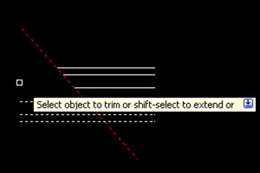
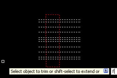
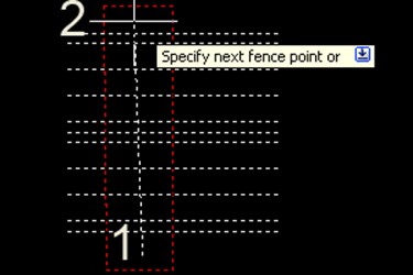

 You might want to take a look at the fence (fe) selection option. This allows you to quickly select the lines you want to trim, by drawing a line across them. Every line that is crossed by the line you draw will be selected and trimmed.
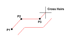
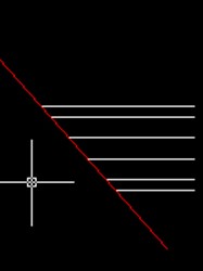
- The extend command
With the extend option you can shorten or lengthen objects to meet the edges of other objects. For example a line can be exactly fitted between objects. Extending a object works in the same way as trimming.
To extend: Click the Extend command; optionally select the object you want to extend to; select the line(s) you want to extend.


![]()
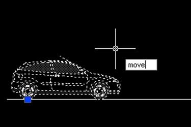
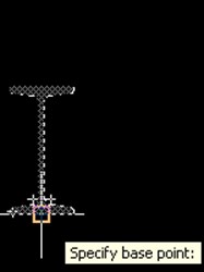
- The move command
The move command is used to move one or more objects from one point to another.
Select the objects and specify the base point. The base point is essentially the point where you ‘grab’ the objects. So if you input coordinates, the base point is the point where the coordinates relate to. Moving an object can either be done with the aid of object snap, or by using relative coordinates.

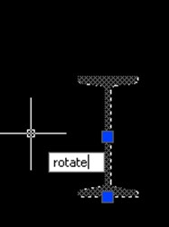
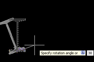
 The rotate command
 The rotate command
You can rotate objects with an absolute or relative angle. When using an absolute angle: Specify the base point and then specify the rotation angle.


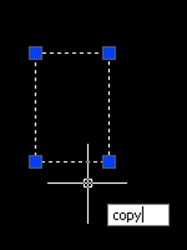
- The copy command
The copy command is used to copy an object
Method: Select objects, press copy and specify a base point (in a similar way as with the move tool)
Now you can position the object in the same way as you would with a starting point of a line.

 The array command
 The array command
The array command is used to create copies of objects in a rectangular or polar pattern. This is especially useful when you need to duplicate several objects at the same distance from each other (columns in a parking garage for instance).
After clicking on the array button the following screen will appear:
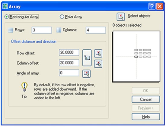
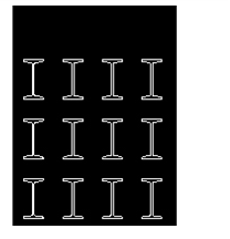
In this screen we need to input the number of Rows (horizontal direction) and Columns (vertical direction) and their respective offset. For example, to create a grid of I-beams, lets first input the number of rows and columns (in this case 3 and 4). Now input the row and column offset: 30 units to the right and 20 units upward.
AutoCAD automatically shows a preview of the array operation in the white square, try experimenting with different values (for instance a negative value instead of a positive one) to see what happens.
 When you’re satisfied with the settings, select the object to use in the row operation, by first clicking on the ‘Select Objects’ button and then on the objects themselves. Finish the selection by pressing [space] or [enter]
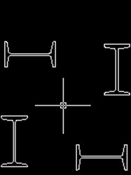
When the array window reappears, select either Preview or OK to execute the array command. In the same manner it’s possible to create a polar array:
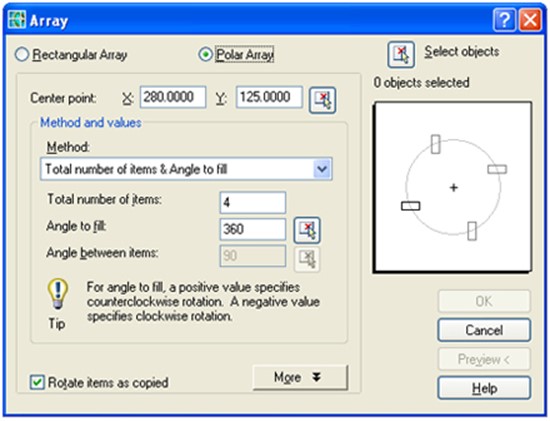
The polar array rotates around the center point which you can select by clicking on the center point button in the array window.

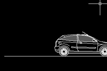
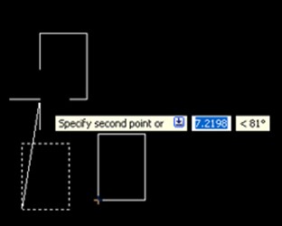
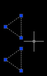
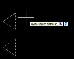
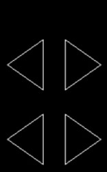
- The mirror command
The mirror command is used to create a mirror image of an object. It is useful for creating symmetrical objects because you can quickly draw half the object and then mirror it instead of drawing the entire object.
You flip the object about an axis called a mirror line to create a mirror image. First select the object. To specify the temporary mirror line, you enter two points. You can choose whether to delete [y] or retain the original [n] object.


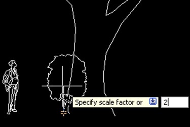
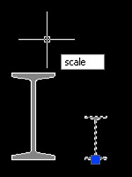
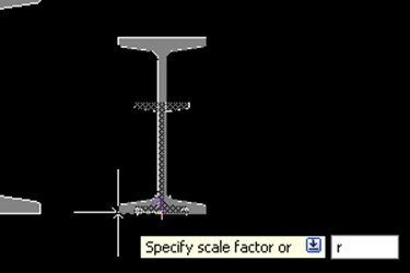
- The scale command
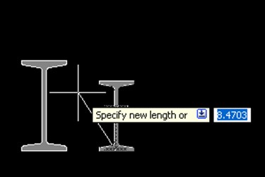
Thescalecommand is used either to enlarge or reduce an object. You can start by specifying a base point and a length which will give a scale factor. A scale factor greater than 1 enlarges the object. It is also possible to scale an object using a reference object. This method scales the object equally in all directions.
Scaling using a scale factor: Select the object; type sc in the command line; scale factor; [enter]
Scaling using a reference: Select the object; type sc in the command line; specify base point; choose r to use reference; specify the reference length of the original object; specify the new length of the original object.


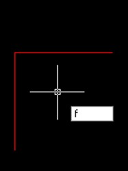
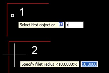
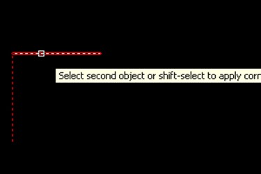
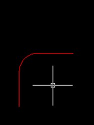
- The fillet command
You can use the fillet tool to connect two objects with an arc with a specified radius. The inside corner is called a fillet and an outside corner is called a round.
To fillet: type f in the command line; type R for the radius (optional); specify the radius; [enter]; select the first line; select the second line.
Chamfer is almost identical, but it will will make a straight line instead of an arc.

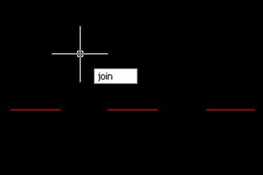
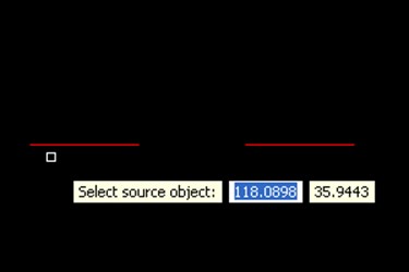
- The Join command
The join tool can be used to combine similar objects into one single object. It is also possible to create complete circles from arcs.
The object you want to join is called the source object. And the objects you want to join have to be located in the same plane.
To join: Type j in the command line; select the source object; select the lines to join to the source object.
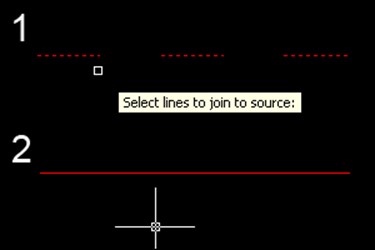
If you use AutoCAD 2009 or older, you can only join lines when the endpoints of the lines are on one point.

- The explode command
Polylines, hatches or blocks can be converted into individual elements with the explode option.
If you explode a polyline, every segment will become a separate line.
To Explode a block: First select the block; type ex; [enter].


General evaluation questions
- State six types of modify tools
- Differentiate between fillet and chamfer.
- State four types of computer component.
- Describe the step you will undergo in using fillet tool to draw an elbow.
Reading assignment
1. Use www.google.com to search.
2. Use www.google.com to search AutoCAD
Weekend Assignment
Objective
- The part of a computer that displays the result of the processed data is called A. input unit. B. output unit.
 C. control unit. D. ALU.
 C. control unit. D. ALU.
- The command tool shown above is called A. fillet. B. trim. C. line. D. offset.
- ……………………is used for storing data to be processed and the instruction for processing. A. Memory.
B. Control. C. Output. D. CPU.

- The draw tool shown above is calledA. polyline. B. rectangle. C. array. D. arc.
- The following are examples of modifying tools except A. extend. B. fillet. C. spline. D. mirror
Theory
- Differentiate between modify and draw tools.
- Draw a cube of side 50mm using AutoCAD package