WEEK EIGHT:
Topic: Auxiliary views
Content:
(i) Meaning of auxiliary projection.
(ii) Auxiliary projection of prisms
(iii) Auxiliary projection of cones.
Meaning of auxiliary projection.
Auxiliary projection: The normal principal planes of projection; the vertical plane VP and the horizontal plane HP used in orthographic projection do not sometimes provide or show sufficient information about parts with inclined or sloppy surfaces. It is therefore important to form another plane which is parallel to these inclined surfaces in order to obtain their true shapes and sizes. The planes of projection and the direction of view used in this case are called the auxiliary planes of projection.
Note: The auxiliary view obtained from the normal front elevation is called “first auxiliary plan” while that obtained from the normal plan is called “first auxiliary elevation”. Other auxiliary views obtained from the first auxiliary views are called “second auxiliary views. See figure below for illustration of auxiliary views.
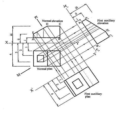
Rules for drawing an auxiliary plan.
(i) Draw the given normal elevation and normal plan taking note of the direction of view which may either be
shown by an arrow such as K or the inclination of the ground line at an angle.
(ii) Draw a ground or datum line X1-Y1 at any convenient distance from the elevation and at right angle to the
direction of view of arrow K.
(iii) Project lines from all the corners of the normal elevation at right angle to the new ground line X1-Y1. Note
that the corners that are visible to the eyes are represented in solid lines while those that are not visible to the
eyes are drawn with short dashes.
(iv) Transfer distances from the normal plan to locate the shape and size of the first auxiliary plan.
Rules for drawing an auxiliary elevation
(i) Same as the steps for drawing auxiliary plan.
(ii) Draw a ground line X2-Y2 at right angle to the direction of the view ie M.
(iii) Project lines from the corners of the normal plan at right angle to the new ground
line X2-Y2. Visible corners are represented in solid lines while invisible corners are represented in short
dashes.
(iv) Transfer distances from the normal elevation to get the shape and size of the first auxiliary elevation.
Evaluation Questions
1. Distinguish between auxiliary projection and orthographic projection?
2. Explain the following terms: (i) First auxiliary elevation. (ii) First auxiliary plan.
Auxiliary projection of prisms
Note: Prisms are named based on the shape of their bases which could either be square, triangular or
 rectangular.
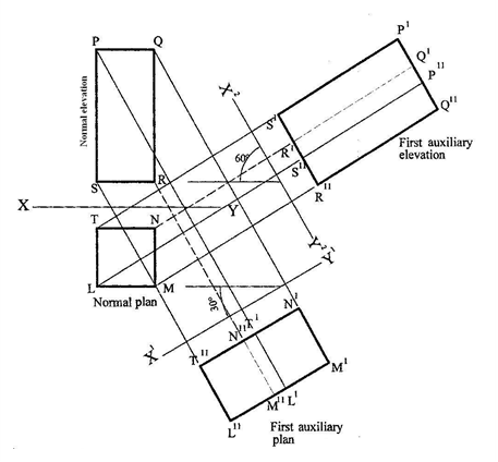
Example: Draw the auxiliary views of a right square prism shown below.
To draw the first auxiliary plan – project lines from elevation; transfer distances from plan
Method:
(i) Draw the given normal elevation and normal plan.
(ii) Draw a ground or datum line X1-Y1 using its angle of inclination as shown in the given question.
(iii) Using a setsquare and a ruler, project lines from all the edges of the normal elevation ie P, Q, R and S
perpendicular to the ground line X1-Y1 and produced beyond it.
(iv) Transfer distances from the normal plan and mark them off on each respective projection line from P,Q,R
and S to obtain the corresponding points T1L1,N1M1,N11M11 and T11L11. This is the first auxiliary plan.
To draw the first auxiliary elevation-project lines from plan; transfer distances from elevation
Method:
(i) Draw a new ground line X2-Y2 using its given angle of inclination as shown in the question.
(ii) Using a setsquare and a ruler, project lines from all the edges of the normal plan ie L,M,N and T
perpendicular to the ground line X2-Y2 and produced beyond it.
(iii) Transfer distances from the normal elevation and mark them off on each respective projection line from
L,M,N and T to obtain the corresponding points S1P1,R1Q1,R11Q11 and S11P11. This is the first auxiliary
elevation.
Evaluation Questions
The diagrams below show the normal elevation and plan of a square prism.
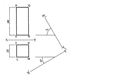 Draw full size the following views: (i) The given views (ii) First auxiliary elevation. (iii) First auxiliary plan.
Auxiliary projection of cones
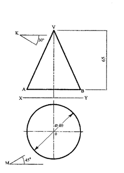
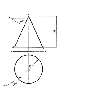
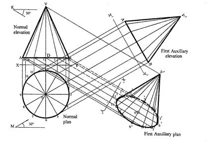 Example: Draw the auxiliary view of a right cone shown below whose vertical height is 60mm and base diameter ф30mm.
To draw the given views
Method:
(i) Draw the given front elevation and plan using the specification provided.
(ii) First, draw a circle of diameter ф30mm and divide it into 12 equal parts.
(iii) Project these divisions upwards to line AB to start the construction of the front elevation. First mark off the
vertical height DV equal to 60mm. Then, radiate points 9, 10, 11, 1, 2, and 3 to point V.
(iv) Indicate the direction of views as given.
To draw the first auxiliary plan – project lines from elevation; transfer distances from plan
Method:
(i) Project lines from points 9,10,11, 12,1, 2 ,3 and V on the normal elevation parallel to the direction of arrow
K.
(ii) Draw a new ground line X1-Y1 at right angle to these projected lines and at any convenient distance from
the elevation.
(iii) Transfer distances from the normal plan and using the ground line as reference line, mark off these
distances on each respective projection line ie points 91, 10181, 11171,121 01 61, 1151, 2141, 31. To locate the
vertex V1, draw a vertical line at 01, perpendicular to line 12-61 and this line cuts the projected line from V
at V1 then radiate lines from V1 to other points to get the first auxiliary plan.
To draw the first auxiliary elevation-project lines from plan; transfer distances from elevation
Method:
(i) Project lines from all the divisions on the circle parallel to the direction of arrow M but perpendicular to a
new ground line X2-Y2 which is drawn at any convenient distance from the normal plan.
(ii) Transfer distances from the normal elevation and using the ground line X2-Y2 as reference line, mark off
these distances on each respective projection line to obtain the first auxiliary elevation.
 Evaluation Questions
The diagram shown below represents the normal elevation and plan of a right cone. Draw full size the following views: (i) The given views (ii) First auxiliary elevation. (iii) First auxiliary plan.
General Evaluation/Revision Questions
1. With the aid of diagrams, state 7 types of line and their uses
2. ABCD is a rectangle. Diagonal AC is 80mm long while length AB is 65mm. Construct the rectangle.
How long is the width of the rectangle?
3. An ellipse has major axis 120mm and minor axis 80mm. (a) Construct the ellipse using: (i) focal point
method. (ii) Concentric circle method. (iii) intersecting line or rectangle method.
(b) Construct a tangent at a point 30mm above the major axis and to the right of the minor axis.
Reading assignment
Technical drawing for school certificate and GCE by J.N. Green pages116 – 122
Weekend Assignment
Objective
1. Which of the following views are relevant measurements taken in drawing the second auxiliary elevation?
A. first auxiliary elevation only. B. First auxiliary elevation and first auxiliary plan. C. Standard elevation
and first auxiliary plan. D. Second auxiliary plan and first auxiliary plan.
2. From which view is the second auxiliary elevation projected? A. First auxiliary elevation.
B. First auxiliary plan. C. Second auxiliary plan. D. Standard elevation.
3. Which of the following is not used when projecting the second auxiliary elevation? A. First auxiliary plan.
B. Normal elevation. C. Normal plan. D. None of the above.
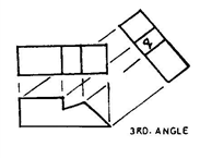
 4. The view labelled q in the diagram above is called A. auxiliary plan. B. end elevation. C. auxiliary elevation. D. front elevation.
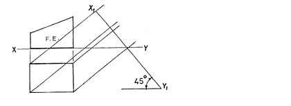
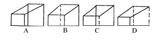
5. Which of the following represents the auxiliary view of the casting on X1Y1?
Theory
 The diagram shown below represents the normal elevation and plan of a right cone. Draw full size the following
views: (i) The given views (ii) First auxiliary elevation. (iii) First auxiliary plan.