WEEK NINE:
Topic: Auxiliary views
Content:
(i) Auxiliary projections of cylinders.
(ii) Auxiliary projections of cubes.
(iii) Auxiliary projections of Pyramids.
Auxiliary projection of cylinders
Example: Draw the auxiliary views of a right cylinder of height 50mm and base diameter ф30mm.
To draw the first auxiliary plan ( project lines from elevation; transfer distances from plan)
Method:
(i) Draw the given elevation and plan as follows.
(ii) Divide the plan (circle) into 12 equal parts.
(iii) Project these divisions upwards to the X-Y line and then produced to the bottom and top of the cylinder.
These projected lines meet the bottom of the cylinder at 0,1,2,3,4,5 and 6 and the top at 01,11,21,31,41,51
and 61.
(iv) Project lines from the bottom and top of the cylinder parallel to the direction of view ie arrow A.
(v) Draw a new ground line X1-Y1 at right angle to these projected lines and at any convenient distance from
the elevation.
(vi) Transfer distances from the normal plan and using the ground line X1-Y1 as reference line, mark off
these distances on each respective projection line just as it was done to get the base of the first
auxiliary plan of the cone above. This should be done for the projection lines from both the bottom
and top of the elevation. Then join the points together to finish the first auxiliary plan.
To draw the first auxiliary elevation (project lines from plan; transfer distances from elevation)
Method:
(i) Project lines from all the divisions on the plan (circle) parallel to the direction of arrow B but
perpendicular to a new ground line X2-Y2 which is drawn at any convenient distance from the
normal plan.
(ii) Transfer distances from the normal elevation and using the ground line X2-Y2 as reference line, mark
 off these distances on each respective projection line to obtain the first auxiliary elevation.
Evaluation Questions
The figure below is a cylinder in orthographic projection. Draw the given views and show the following:
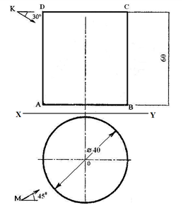 (i) The given views. (ii) First auxiliary plan. (iii) First auxiliary elevation
![]()
Auxiliary projection of Cubes
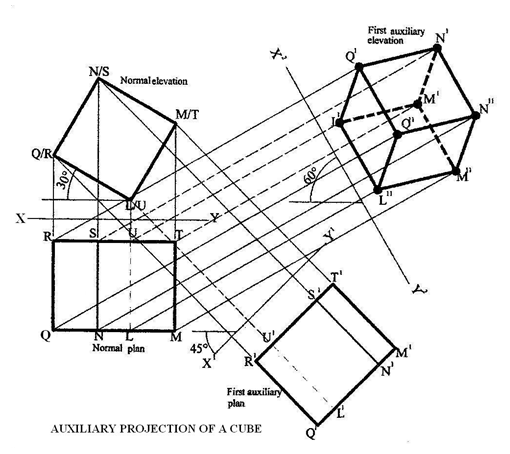 Example: Draw: (i) The plan (ii) the first auxiliary plan and (iii) the first auxiliary elevation of a cube inclined at
an angle of 300 to the horizontal as shown below.
To draw the first auxiliary plan (project lines from elevation; transfer distances from plan)
Method:
(i) Draw the elevation and plan as follows.
(ii) Using L/U as the lowest point, construct the elevation L/U, M/T, N/S and Q/R inclined at an angle of
300
(iii) Project these points in (ii) downwards to draw the normal plan as seen in the diagram below.
(iv) Project lines from the edges of the normal elevation ie points L/U, M/T, N/S and Q/R perpendicular
to a new ground line X1-Y1 and produced beyond it.
(v) Using X-Y as the reference line, transfer distances from the normal plan and using the ground line
X1-Y1 as reference line, mark off these distances on each respective projection line to get points that
produces the first auxiliary plan.
To draw the first auxiliary elevation-project lines from plan; transfer distances from elevation
Method:
(i) Draw a new ground line X2-Y2 using its given angle of inclination as shown in the question.
(ii) Using a setsquare and a ruler, project lines from all the edges of the normal plan ie points R, S, U ,T
and Q, N, L,M perpendicular to the ground line X2-Y2 and produced beyond it.
(iii) Transfer distances from the normal elevation and mark them off on each respective projection lines
from R, S, U, T which form the top of the cube ie R11, S11, U11,T11 and those from Q, N, L,M which
form the bottom of the cube ie Q11, N11, L11, M11. This is the first auxiliary elevation.
Evaluation Questions
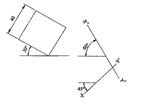 The figure below is a cube inclined at an angle of 300 to the horizontal. Draw the: (i) plan (ii) the first
auxiliary plan and (iii) the first auxiliary elevation.
Auxiliary projection of pyramids
Note: Pyramids are named by the shape of their bases which could either
be square, triangular, rectangular, hexagonal etc.
Example: The figure below is a hexagonal pyramid in orthographic projection.
Draw the views and show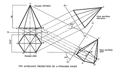 the following: (i) First auxiliary plan. (ii) First auxiliary elevation.
To draw the given views
Method:
(i) Draw a circle of diameter ф35mm and construct a hexagon of sides CEBEDA on it using 600
setsquares.
(ii) Project lines upwards from the edges and centre of the hexagon to line AB.
(iii) Produce the centre line beyond the base and mark off the vertical height OV.
(iv) Radiate lines from A, C/D, O, E/F and B to point V.
(v) Indicate the direction of views as shown in the question.
To draw the first auxiliary plan (project lines from elevation; transfer distances from plan.)
Method:
(i) Project lines from points A, C/D, O, E/F, B and V on the normal elevation perpendicular to the
direction of the ground line X1-Y1 and produced beyond it.
(ii) Using X-Y as reference line, transfer distances from the normal plan and using the ground line X1-Y1
as reference line, mark off these distances on each respective projection line ie points
A1,C1D1,O1,E1F1,B1 and V1. To locate the vertex V1, draw a vertical line at 01, perpendicular to the
centre line O-O1and this line cuts the projected line from V at V1.Then, radiate lines from V1 to
A1,C1,D1,O1,E1,F1,and B1 to get the first auxiliary plan.
To draw the first auxiliary elevation-project lines from plan; transfer distances from elevation
Method:
(i) Project lines from all the edges, A, C, E, B, F, D and the centre O of the normal plan perpendicular to
a new ground line X2-Y2 which is drawn at any convenient distance from the normal plan but
inclined at an angle of 600.
(ii) Transfer distances from the normal elevation and using the ground line X2-Y2 as reference line, mark
off these distances on each respective projection line to obtain the first auxiliary elevation.
Evaluation Questions
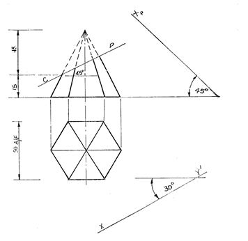 The figure shown below is a hexagonal pyramid in orthographic projection. Draw the: (i) given views (ii) first
auxiliary plan. (iii) first auxiliary elevation.
General Evaluation/Revision Questions
1. Draw title blocks for Architects and Engineers on a plane paper.
2. With the aid of a sketch diagram, explain the difference between datum and chain dimensioning
respectively.
3. The size of your room measures 4m by 6m. Calculate to the nearest whole number, the number of square
tiles of size 30cm that would be needed to finish the tiling work?
4. A point on the circumference of a circle, diameter 70mm, rolls along a straight line without slipping.
(i) Trace the locus of the point as the circle completes one revolution. (ii) Name the locus.
5. Draw diagrams to show the following butt joints. (i) Single- V butt . (ii) Double- J butt.
(iii) Single-bevel butt.
Reading assignment
Technical drawing for school certificate and GCE by J.N. Green pages116 – 122
Weekend Assignment
Objective
1. An auxiliary view that is projected from the first auxiliary elevation is called? A. First auxiliary
plan. B. Second auxiliary elevation. C. Second auxiliary plan. D. First auxiliary elevation.
2. From which views are relevant measurement taken in drawing the second auxiliary elevation?
A. First auxiliary elevation only. B. First auxiliary elevation and first auxiliary plan.
C. Second auxiliary plan and first auxiliary plan. D. Standard elevation.
3. An auxiliary view projected from a normal elevation is called? A. First auxiliary elevation.
B. Auxiliary plan. C. Auxiliary elevation. D. First auxiliary plan.
4. A view which is drawn on a plane other than the normal principal planes of projection is called?
A. Oblique. B. Isometric. C. Auxiliary. D. Orthographic.
5. An auxiliary view projected from a normal plan is called? A. Auxiliary plan. B. First auxiliary plan.
C. Auxiliary elevation. D. First auxiliary elevation.
Theory
1. The figure 1 shown below is a hexagonal pyramid in orthographic projection. Draw the: (i) given
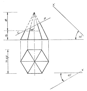
![]() views (ii) first auxiliary plan. (iii) first auxiliary elevation.
views (ii) first auxiliary plan. (iii) first auxiliary elevation.
2. The figure below shows a frustum of a right cone. Draw the: (i) given elevation (ii) complete orthographic
 plan (iii) complete auxiliary plan viewed in the direction of arrow P.