SECOND TERM E-LEARNING NOTE
SUBJECT: TECHNICAL DRAWING
CLASS: SS2
TITLE: SECOND TERM SCHEME OF WORK
WEEK 1: Revision work on pictorial drawing.
WEEK 2-3: Orthographic projection
WEEK 4-5: Conversion of orthographic views to isometric
WEEK 6-7: Perspective drawings
WEEK 8-9: Auxiliary views.
WEEK 10: Lines in space.
WEEK 11: Introduction to building drawing.
WEEK 12: Revision and examination.
Reference materials:
Technical drawing by J.N. Green.
Engineering drawing 1 by M.A.Parker and F.Pickup
Metal work technology by G.H. Thomas.
Drafting Technology and practice by William P. Spence
Technical Drawing by F.B Mayock ( 1- 4 )
Basic technology for junior secondary schools book 1 by G.N Nneji, E.J. Okon, V.C. Nwachukwu, N.A. David, and T.C. Ogbuanya. Pages 1-17, 34-78.
Basic technology for junior secondary schools book 2 by I. Elekwa , O.A. Bamiro, A.O. Oluyide,
D.L Ladoye, A. Nurudeen and I.O. Akuru
Technical drawing for senior secondary schools by Y.A Thanni and C.A Faseun-Motesho Pages 97-103
WEEK ONE
Revision work on pictorial drawing-isometric and oblique blocks
![]()
Content:
(i) Isometric drawing.
(ii) Oblique drawing.
Meaning of pictorial drawing
A pictorial drawing as the name implies is that which is represented in its true picture. It is also referred to as three dimensional drawing since it shows the length, height and depth of the object. Pictorial drawing falls into three main groups namely: Isometric, oblique and perspective.
Isometric drawing
This is the type of pictorial drawing in which the receding lines are drawn at 300 to the horizontal and other lines are drawn vertically. All lines are drawn in their true lengths. The axes on which isometric drawing is made is called ‘isometric axes’. Each axis is spaced at an angle of 1200
from each other as shown below. An axis may be placed at any position provided it is 1200 apart from the next one.
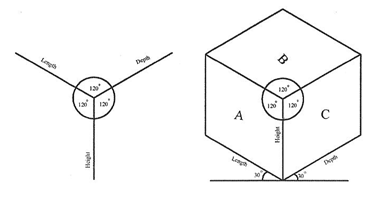
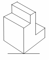
Fig. Isometric axes Fig. A cube Fig. A solid block
Isometric scale-: This is the scale used in finding the true isometric projection of an object from
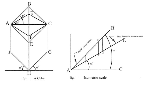 the normal conventional isometric {equal angular measurement} projection. See the figures below
for more illustration.
Method:
(i) Draw line AC. This is one of the diagonals of the face ABCD of the cube shown in figure 6.
(ii) Construct line AB such that AB is inclined at an angle of 450 to AC
(iii) Construct line AE such that AE is inclined at an angle of 300 to AC. Therefore, AB represents
the measurement of the object while AE is the true isometric measurement of the object.
Note: Any measurement made or taken along line AB is the object measurement such as A1, A2 and A3. The perpendicular lines drawn from these points to line AE will mark points 11, 21 and 31. Thus the measurement A11, A21 and A31 are the true isometric measurements.
Drawing of objects in isometric: Any object no matter how complicated it is, could easily be drawn. For example, carefully follow the steps in construction of the figure below.
Circles, arcs and curves in isometric
Circles in isometric: Circle in isometric form appears like an ellipse. There are different methods of drawing a circle in isometric projection and these include: Four-centered approximate ellipse, ordinate or grid and offset methods.
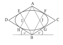
Four-centered approximate ellipse method
 For instance, to draw a circle of diameter 2cm in isometric using the four-centered method, follow the
procedures below:
Fig. Four-centre method
Method:
(i) Draw a square in isometric equal in size to the diameter of the given circle. Bisect each side.
(ii) From point A, draw lines to meet the mid-points of line BD and BC at H and G respectively.
(iii) Repeat the procedure in (iii) with point B to get points E and F respectively.
(iv) The point of intersection of these lines i.e. I and J are centers of arc.
(v) With I as centre and radius IE or IF, draw an arc EH. Repeat same with center J to draw arc FG.
(vi) With A and B as centres draw arcs GH and EF respectively to complete the circle.
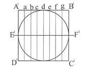
Ordinate or Grid method
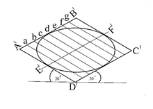
 For instance, to draw a circle of diameter 2cm in isometric using the ordinate or grid method, follow the procedures below:
Normal circle Isometric circle
Method:
(i) Construct a square A1B1C1D1 of same diameter to enclose the given circle in orthographic.
(ii) Draw a line E1F1 as the horizontal diameter of the circle.
(iii) Divide the square into any number of equal parts called ordinate or grid i.e. a, b, c, d, e, f and g .
as the case may be. Take note of the distances of the points where each grid cuts the circle.
(iv) Construct a square A1B1C1D1 of same diameter in isometric and repeat exactly the same division as
in the plane square on it.
(v) Transfer distances along each grid of the normal square to its corresponding grid of the isometric
square. The positions of these distances mark out the circle in isometric. See figures above.
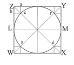
Offset method
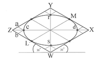
 For instance, to draw a circle of diameter 2cm in isometric using the offset method, follow the procedures below:
Normal circle Isometric circle
Method:
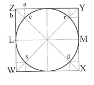
(i) Construct a square WXYZ of equal size as the given circle to enclose it.
(ii) Determine the mid points L, Q, M and P of the square.
(iii) Draw diagonals WY and XZ.
(iv) Determine the points c, r, d and s where the diagonals cut the circle.
(v) Draw a square in isometric of same size as the square in (i)
(vi) Repeat steps (ii) and (iii).
(vii) Transfer the lengths Z-a and Z-b of the plane square to the isometric square to get point c. Use same method for points r, d, and s respectively.
(viii) Join points c, P, r, M, d, Q, s and L to get the circle in isometric form.
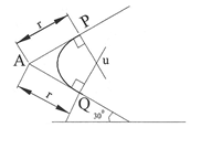 Drawing of arcs in isometric: The method of drawing arcs in isometric is the same as the four- centered method of drawing circles. Here, it is not necessary to draw the entire isometric square since an arc is only a part of circle.
Method:
(i) From the corner A where the arc is to be drawn, lay off the radius r of the arc equally on both
edges.
(ii) From each of these points P and Q respectively, draw perpendicular lines
(iii) The point of intersection u of these perpendicular lines marks the center of the arc to be drawn.
With u as centre and radius uP or uQ draw the required arc PQ.
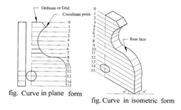
Drawing of irregular curves in isometric: The ordinate or grid method of drawing circles in isometric is appropriate for this purpose. This is done by drawing lines or ordinates at equal spacing on the orthographic view of the object to the same scale as the isometric. Distances are then transferred with a divider on the isometric axis of the object to be drawn. See the figures below for more illustration.
`
Method:
(i) Draw a series of equally spaced parallel lines (ordinates) on the given plane view.
(ii) Where each ordinate line intersects the curve forms a coordinate point.
(iii) Draw an isometric axes of the same dimensions as the given plane view.
(iv) Repeat step (i) on the drawn isometric axes.
(v) With a pair of dividers, transfer the coordinates of the plane view to the isometric view. The rear
face ie the thickness is drawn the same way.
Evaluation Questions
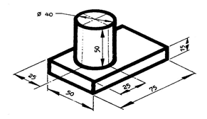
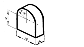 1. Draw the block shown below in isometric.
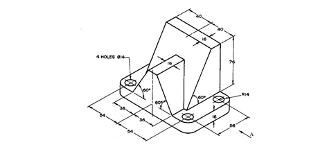
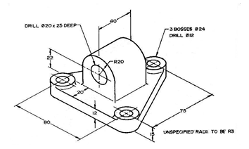 2. Draw full size in isometric projection the pivot block shown below.
Oblique drawing
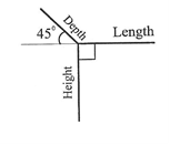
Oblique drawing uses three axes just like isometric drawing. In oblique drawing, two of the oblique axes are placed at right angle to each other. The third axis (receding) is placed at any convenient angle (300, 450 or 600) to the horizontal. See the figures below for oblique axes. All receding edges are drawn parallel to this third axis.
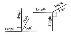
 There are three classifications of oblique drawing. These include cavalier, cabinet and general oblique respectively.
Fig. Oblique axes
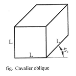 Cavalier oblique- This is the type of oblique in which the receding axis (depth) makes any angle usually 300 or 450 with the horizontal and is drawn full length there by having equal length with the depth and height. See diagram below. The depth of the cube appears to be longer than the length and height. Actually, they are equal. This distortion could be eliminated by reducing the angle of the receding axis.
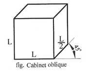 Cabinet oblique- Cabinet oblique used the same principles of construction with cavalier oblique except that the receding axis which could be drawn at any angle of either300, 450 or 600 to the horizontal is actually drawn half full length.
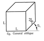 General oblique- This is one in which the receding axis (depth) could be drawn to lengths ranging from half to full length. The scale is reduced until the object appears most natural. The angle between the receding axis and the horizontal is usually drawn between 300 and 600.
Circles, arcs and curves in oblique
Drawing of circles and arcs in oblique: Circles and arcs in oblique are drawn almost the same way as in isometric drawing. Cavalier oblique can be drawn by using the four-centered method while Cabinet and General oblique on the other hand can be drawn using the offset method. For example, to draw a circle of size 2cm in diameter, see the application of these methods below.
Four-centered approximate ellipse method
 For instance, to draw a circle of diameter 2cm in cavalier oblique using the four-centered method, follow the procedures below:
Method:
(i) Draw a square on the receding axis equal in size to the diameter of the circle to be drawn.
(ii) Bisect all the sides of the square to get the mid point of each side.
(iii) From each midpoint, erect a perpendicular line towards the inside of the square.
(iv) The points of intersection of these perpendicular lines mark the four centers of the arcs that draw
the circle.
Note: If the angle which the receding axis makes with the horizontal is less than 300, these perpendiculars will intersect inside the oblique square. Otherwise, they will intersect outside the oblique square.
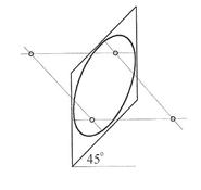
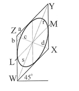 Offset method: The procedures is the same as isometric. See diagram below for more illustration.
Normal circle Oblique circle
General evaluation/ revision questions
1. Using off-set method, draw a circle 40 mm diameter in oblique projection.
2. Explain the following types of oblique drawing (a) Cavalier (b) Cabinet
3. Draw full size the block shown below in oblique projection.

Reading assignment
Technical drawing by J.N Green Pages 156-161
Weekend Assignment
Objective
1. The type of pictorial drawing in which one of the receding axis is drawn at right angle is called ——-
A. isometric. B. oblique. C. perspective D. axonometric.
2. Which of the following types of oblique projection has its receding axis drawn full length? ——-
A. cabinet B. cavalier C. Oblique D. offset.
3. Isometric axes are spaced from each other at an angle of A. 1200. B. 1350. C. 300 D. 450
4. Oblique axes are spaced from each other at an angle of A. 1200. B. 1350. C. 300 D. 450
5. The receding lines of an isometric drawing are drawn at what angle to the horizontal? A. 600 B. 450 C. 300
D. 900
Theory
 1. Draw full size in isometric projection the object shown below.
 2. Draw full size the bolster block s
![]() hown below in isometric..
hown below in isometric..
Thanks for making this material available to the public, but I would like to request of you to make it a single book either in pdf or word format and also make accessible in a downloadable format.