WEEK TEN:
Topic: Lines in space
![]() Content:
Content:
(i) Meaning of traces and the true length of a line.
(ii) Methods of determining the true length and inclination of lines in space.
.Meaning of traces and the true length of a line.
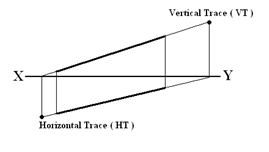
Trace: A line inclined to a normal principal plane of projection would if produced penetrates this plane. The point where this happens is called a trace. The true or actual
length is the length of this inclined line obtained when it is projected on an auxiliary plane parallel to it.
Methods of determining the true length and inclination of a line in space.
1. Auxiliary method: This method is the same as that used in auxiliary projection of inclined surfaces of objects treated earlier on.
 Example 1: Determine the true length and angle of inclination of a line AB inclined in space as shown in figure below.
Method:
(i) Draw the X-Y line.
(ii) Draw the plan AB and the elevation A1B1 of the line.
(iii) Draw the projection lines AA1 and BB1.
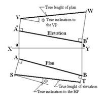
(iv) To obtain the true length of the normal plan AB, project lines at right angle from the ends A1 and B1 of the normal elevation and using line X-Y as the reference line, transfer the distances aA and bB of the normal plan and mark them off respectively to locate points V on the perpendicular line from A1 and W on the perpendicular line from B1. Line VW is the true length of the plan and it is inclined to the vertical plane VP at an angle ф
(v) To obtain the true length of the normal elevation A1B1, project lines at right angle from the ends A and B of the normal plan and using line X-Y as the reference line, transfer the distances aA1 and bB1 of the normal elevation and mark them off respectively to locate points S on the perpendicular line from A and T on the perpendicular line from B. Line ST is the true length of the elevation and it is inclined to the horizontal plane HP at an angle Ө.
2. Rebatment or revolution method:
 Example 1: Consider an oblique line AB which is inclined at an angle of 300 to the vertical plane and 450 to the horizontal plane.
Method:
(i) Draw the usual X-Y line.
(ii) Draw the plan and elevation of line AB.
(iii) Draw a line to connect the elevation and plan i.e. line bB.
To draw the true length TL of the elevation Aa and its true angle of inclination to the horizontal plane HP.
(iv) With a pair of compasses pin at point A and radius AB, swing an arc to meet the X-Y line at point
m and then project a vertical line upwards from this point.
(v) Take the distance ab and mark it off on this line to get point b1.
(vi) Draw a horizontal line to connect b to b1. Line Ab1 is the true length TL of the elevation and its
angle of inclination to the horizontal plane HP is measured.
To draw the true length TL of the plan AB and its true angle of inclination to the vertical plane VP.
(vii) With A as centre and radius Ab, swing an arc to meet the X-Y line at point n and then project a
vertical line downwards from this point.
(viii)Take the distance aB and mark it off on this line from point m to get point B1.
(ix) Draw a horizontal line to connect B to B1. Line AB1 is the true length of the plan and its true angle
of inclination to the vertical plane VP is measured.
Determination of the true shape of a triangular lamina
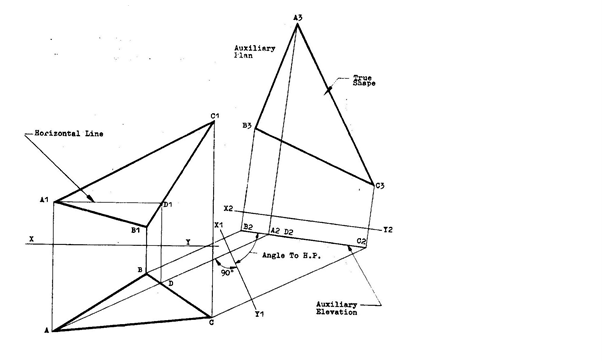
Method
- Draw the given elevation and plan of the lamina with the ground line X-Y drawn between them.
- Determine point D on the plan by drawing a horizontal line parallel to the ground line X-Y from point A1 to D1 then draw a line vertically down to point D.
- Project a line from point A through D to a convenient point. Similarly, project lines from points B and C parallel to AD produced.
- Draw a ground line X1-Y1 perpendicular to the projected lines from the plan.
- Obtain distances from X-Y line to points A1,B1 and C1 on the elevation and transfer them, now from X1-Y1 respectively to obtain the auxiliary elevation line B2, A2D2 and C2.
- Similarly, obtain distances from the X1-Y1 to points A,B,C and D on the plan and transfer them to obtain the auxiliary plan A3, B3, C3 now using X2-Y2 as the ground line..
Evaluation question
The figure shown below is the elevation and plan of a triangular lamina in first angle projection.
- Draw the true shape of the lamina
- Measure and state the
- Angle of inclination to the horizontal plane
- True length of AC.
- Indicate on the drawing, the;
- auxiliary elevation;
- auxiliary plan.

 Determination of the true shape of a triangular lamina having one of its faces resting on the horizontal line.
Method
- Draw the elevation and plan of the lamina with the face AB lying on the horizontal plane.
- Draw B1A1 produced to a convenient point D.
- Erect a perpendicular DE at point D.
- Draw a line from C1T parallel to B1D and mark off the vertical height HT on this line.
- With a compass pin at point H and radius HT, swing an arc to meet DE at G.
- Draw a line from G parallel to HC1 and this intersect the altitude PC1 produced at point K.
- Join KA1 and KB1
Evaluation Questions
1. Determine the true length and angle of inclination of the elevation a1b1 and plan a2b2 inclined in space as shown in figure below using the auxiliary method.

 2. The figure below shows the diagonal of a cube inclined at 450 to both the horizontal and vertical planes. Use rebatment method to obtain the true length and inclination of the diagonal.
Reading assignment
Technical drawing for school certificate and GCE by J.N. Green pages 123-130.
Engineering drawing 1 by M.A.Parker and F.Pickup pages 138 – 148.
Engineering drawing 2 by M.A.Parker and F.Pickup pages 204 – 230.
Weekend Assignment
Objective
1. Which of the following is not a method used to determine the true length of a straight line?
A. 4-center method. B. auxiliary method. C. revolution method. D. rebatment method.
 2. The point at which a line in space, if produced, penetrates a plane is called? A. seam. B. joint line.
C. trace. D. datum.
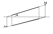
Use the figure below to answer questions 3-5
3. The point N on the diagram above is called? A. seam. B. vanishing point. C. focal point.
D. horizontal trace.
4. The point M on the diagram above is called? A. vanishing point. B. seam. C. horizontal trace.
D. vertical trace.
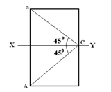
 5. The true length of the oblique line ST in the diagram below is A. SS4 B. S2T C. S1T. D. SS3
Theory
1. The elevation of a line AB is of length 60mm and its plan is 45mm. If the elevation is inclined at an

angle of 450 to the X-Y line. Draw the true length of the plan and elevation and their true inclinations.
2. The figure above shows the plan and elevation of a straight line. The line is inclined to both the
horizontal and vertical planes.
Determine:
(a) the true length of the line.
(b) the true angle of inclination to both planes