Share this:
SECOND TERM E-LEARNING NOTE
SUBJECT: TECHNICAL DRAWING
CLASS: SS2
TITLE: SECOND TERM SCHEME OF WORK
WEEK 1: Revision work on pictorial drawing.
WEEK 2-3: Orthographic projection
WEEK 4-5: Conversion of orthographic views to isometric
WEEK 6-7: Perspective drawings
WEEK 8-9: Auxiliary views.
WEEK 10: Lines in space.
WEEK 11: Introduction to building drawing.
WEEK 12: Revision and examination.
Reference materials:
Technical drawing by J.N. Green.
Engineering drawing 1 by M.A.Parker and F.Pickup
Metal work technology by G.H. Thomas.
Drafting Technology and practice by William P. Spence
Technical Drawing by F.B Mayock ( 1- 4 )
Basic technology for junior secondary schools book 1 by G.N Nneji, E.J. Okon, V.C. Nwachukwu, N.A. David, and T.C. Ogbuanya. Pages 1-17, 34-78.
Basic technology for junior secondary schools book 2 by I. Elekwa , O.A. Bamiro, A.O. Oluyide,
D.L Ladoye, A. Nurudeen and I.O. Akuru
Technical drawing for senior secondary schools by Y.A Thanni and C.A Faseun-Motesho Pages 97-103
WEEK ONE
Revision work on pictorial drawing-isometric and oblique blocks
![]()
Content:
(i) Isometric drawing.
(ii) Oblique drawing.
Meaning of pictorial drawing
A pictorial drawing as the name implies is that which is represented in its true picture. It is also referred to as three dimensional drawing since it shows the length, height and depth of the object. Pictorial drawing falls into three main groups namely: Isometric, oblique and perspective.
Isometric drawing
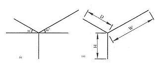
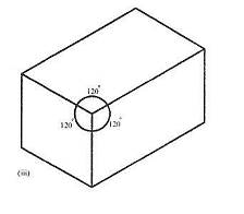
This is the type of pictorial drawing in which the receding lines are drawn at 300 to the horizontal and other lines are drawn vertically. All lines are drawn in their true lengths. The axes on which isometric drawing is made is called ‘isometric axes’. Each axis is spaced at an angle of 1200
from each other as shown below. An axis may be placed at any position provided it is 1200 apart from the next one.

Fig. Isometric axes Fig. A cube Fig. A solid block
Isometric scale-: This is the scale used in finding the true isometric projection of an object from
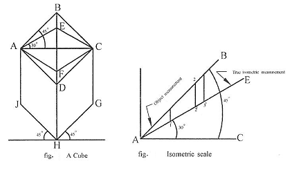 the normal conventional isometric {equal angular measurement} projection. See the figures below
for more illustration.
Method:
(i) Draw line AC. This is one of the diagonals of the face ABCD of the cube shown in figure 6.
(ii) Construct line AB such that AB is inclined at an angle of 450 to AC
(iii) Construct line AE such that AE is inclined at an angle of 300 to AC. Therefore, AB represents
the measurement of the object while AE is the true isometric measurement of the object.
Note: Any measurement made or taken along line AB is the object measurement such as A1, A2 and A3. The perpendicular lines drawn from these points to line AE will mark points 11, 21 and 31. Thus the measurement A11, A21 and A31 are the true isometric measurements.
Drawing of objects in isometric: Any object no matter how complicated it is, could easily be drawn. For example, carefully follow the steps in construction of the figure below.
Circles, arcs and curves in isometric
Circles in isometric: Circle in isometric form appears like an ellipse. There are different methods of drawing a circle in isometric projection and these include: Four-centered approximate ellipse, ordinate or grid and offset methods.
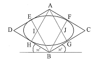
Four-centered approximate ellipse method
 For instance, to draw a circle of diameter 2cm in isometric using the four-centered method, follow the
procedures below:
Fig. Four-centre method
Method:
(i) Draw a square in isometric equal in size to the diameter of the given circle. Bisect each side.
(ii) From point A, draw lines to meet the mid-points of line BD and BC at H and G respectively.
(iii) Repeat the procedure in (iii) with point B to get points E and F respectively.
(iv) The point of intersection of these lines i.e. I and J are centers of arc.
(v) With I as centre and radius IE or IF, draw an arc EH. Repeat same with center J to draw arc FG.
(vi) With A and B as centres draw arcs GH and EF respectively to complete the circle.
Ordinate or Grid method
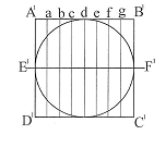 For instance, to draw a circle of diameter 2cm in isometric using the ordinate or grid method, follow the procedures below:
Normal circle Isometric circle
Method:
(i) Construct a square A1B1C1D1 of same diameter to enclose the given circle in orthographic.
(ii) Draw a line E1F1 as the horizontal diameter of the circle.
(iii) Divide the square into any number of equal parts called ordinate or grid i.e. a, b, c, d, e, f and g .
as the case may be. Take note of the distances of the points where each grid cuts the circle.
(iv) Construct a square A1B1C1D1 of same diameter in isometric and repeat exactly the same division as
in the plane square on it.
(v) Transfer distances along each grid of the normal square to its corresponding grid of the isometric
square. The positions of these distances mark out the circle in isometric. See figures above.
Offset method
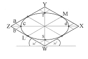
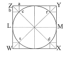 For instance, to draw a circle of diameter 2cm in isometric using the offset method, follow the procedures below:
Normal circle Isometric circle
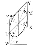
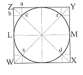
Method:
(i) Construct a square WXYZ of equal size as the given circle to enclose it.
(ii) Determine the mid points L, Q, M and P of the square.
(iii) Draw diagonals WY and XZ.
(iv) Determine the points c, r, d and s where the diagonals cut the circle.
(v) Draw a square in isometric of same size as the square in (i)
(vi) Repeat steps (ii) and (iii).
(vii) Transfer the lengths Z-a and Z-b of the plane square to the isometric square to get point c. Use same method for points r, d, and s respectively.
(viii) Join points c, P, r, M, d, Q, s and L to get the circle in isometric form.
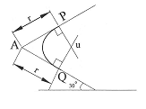 Drawing of arcs in isometric: The method of drawing arcs in isometric is the same as the four– centered method of drawing circles. Here, it is not necessary to draw the entire isometric square since an arc is only a part of circle.
Method:
(i) From the corner A where the arc is to be drawn, lay off the radius r of the arc equally on both
edges.
(ii) From each of these points P and Q respectively, draw perpendicular lines
(iii) The point of intersection u of these perpendicular lines marks the center of the arc to be drawn.
With u as centre and radius uP or uQ draw the required arc PQ.
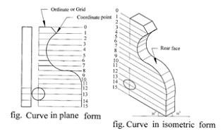
Drawing of irregular curves in isometric: The ordinate or grid method of drawing circles in isometric is appropriate for this purpose. This is done by drawing lines or ordinates at equal spacing on the orthographic view of the object to the same scale as the isometric. Distances are then transferred with a divider on the isometric axis of the object to be drawn. See the figures below for more illustration.
`
Method:
(i) Draw a series of equally spaced parallel lines (ordinates) on the given plane view.
(ii) Where each ordinate line intersects the curve forms a coordinate point.
(iii) Draw an isometric axes of the same dimensions as the given plane view.
(iv) Repeat step (i) on the drawn isometric axes.
(v) With a pair of dividers, transfer the coordinates of the plane view to the isometric view. The rear
face ie the thickness is drawn the same way.
Evaluation Questions
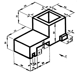
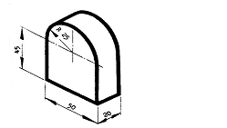 1. Draw the block shown below in isometric.
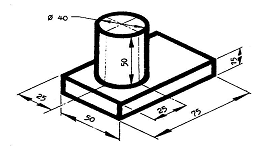
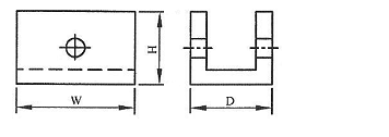
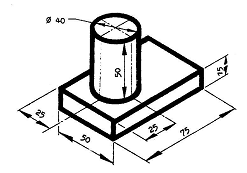
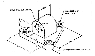 2. Draw full size in isometric projection the pivot block shown below.
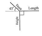
Oblique drawing
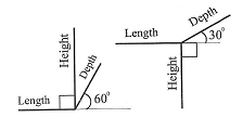
Oblique drawing uses three axes just like isometric drawing. In oblique drawing, two of the oblique axes are placed at right angle to each other. The third axis (receding) is placed at any convenient angle (300, 450 or 600) to the horizontal. See the figures below for oblique axes. All receding edges are drawn parallel to this third axis.
 There are three classifications of oblique drawing. These include cavalier, cabinet and general oblique respectively.
Fig. Oblique axes
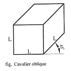 Cavalier oblique- This is the type of oblique in which the receding axis (depth) makes any angle usually 300 or 450 with the horizontal and is drawn full length there by having equal length with the depth and height. See diagram below. The depth of the cube appears to be longer than the length and height. Actually, they are equal. This distortion could be eliminated by reducing the angle of the receding axis.
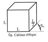 Cabinet oblique- Cabinet oblique used the same principles of construction with cavalier oblique except that the receding axis which could be drawn at any angle of either300, 450 or 600 to the horizontal is actually drawn half full length.
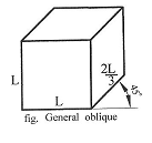 General oblique- This is one in which the receding axis (depth) could be drawn to lengths ranging from half to full length. The scale is reduced until the object appears most natural. The angle between the receding axis and the horizontal is usually drawn between 300 and 600.
Circles, arcs and curves in oblique
Drawing of circles and arcs in oblique: Circles and arcs in oblique are drawn almost the same way as in isometric drawing. Cavalier oblique can be drawn by using the four-centered method while Cabinet and General oblique on the other hand can be drawn using the offset method. For example, to draw a circle of size 2cm in diameter, see the application of these methods below.
Four-centered approximate ellipse method
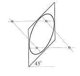 For instance, to draw a circle of diameter 2cm in cavalier oblique using the four-centered method, follow the procedures below:
Method:
(i) Draw a square on the receding axis equal in size to the diameter of the circle to be drawn.
(ii) Bisect all the sides of the square to get the mid point of each side.
(iii) From each midpoint, erect a perpendicular line towards the inside of the square.
(iv) The points of intersection of these perpendicular lines mark the four centers of the arcs that draw
the circle.
Note: If the angle which the receding axis makes with the horizontal is less than 300, these perpendiculars will intersect inside the oblique square. Otherwise, they will intersect outside the oblique square.
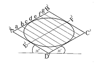
 Offset method: The procedures is the same as isometric. See diagram below for more illustration.
Normal circle Oblique circle
General evaluation/ revision questions
1. Using off-set method, draw a circle 40 mm diameter in oblique projection.
2. Explain the following types of oblique drawing (a) Cavalier (b) Cabinet
3. Draw full size the block shown below in oblique projection.

Reading assignment
Technical drawing by J.N Green Pages 156-161
Weekend Assignment
Objective
1. The type of pictorial drawing in which one of the receding axis is drawn at right angle is called ——-
A. isometric. B. oblique. C. perspective D. axonometric.
2. Which of the following types of oblique projection has its receding axis drawn full length? ——-
A. cabinet B. cavalier C. Oblique D. offset.
3. Isometric axes are spaced from each other at an angle of A. 1200. B. 1350. C. 300 D. 450
4. Oblique axes are spaced from each other at an angle of A. 1200. B. 1350. C. 300 D. 450
5. The receding lines of an isometric drawing are drawn at what angle to the horizontal? A. 600 B. 450 C. 300
D. 900
Theory
 1. Draw full size in isometric projection the object shown below.
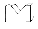
 2. Draw full size the bolster block s
![]() hown below in isometric..
hown below in isometric..
WEEK TWO-THREE:
Topic: Orthographic projection .
Content:
(i) Principal planes of projection.
(ii) First angle orthographic projection.
(iii) Third angle orthographic projection.
Principal planes of projection
The views of a multisided solid object are made by projecting them on to planes (flat surfaces) called planes of projection. The angle at which these views are being projected matters. For instance, if a physics student in the Laboratory decides to concentrate a beam of light rays on an object and thus producing an image (shadow) on a screen, the following can be deduced from this experiment which will further help in understanding the terms used in Orthographic projection. The screen on which the image (shadow) is formed is called the “plane of projection”, the image formed on the screen is called the “projection” or view, and the beam of light rays projected on the object is called projectors. If these projectors are parallel to each other and normal to the plane on which the views are made, such views are called orthographic (right angle) views or projections.
It should be noted that since the projectors are parallel and normal to the plane, they will show the true shape and size of the object being considered.
There are two main planes called the principal planes used in orthographic projection and these include: the horizontal plane and the vertical plane. In practice a third plane called auxiliary vertical plane is needed to adequately describe the shape and size of an object.
These two principal planes intersect to form four (4) quadrants or angles. See diagram below .The object to be drawn is assumed to be placed in one of these quadrants and the views are then projected on the planes. Note that the object may have any orientation to the planes but should be placed in such a way that its main faces are parallel to the planes in order to produce their true shapes and sizes. A view projected on the vertical plane is called the “elevation” whereas that projected on the horizontal plane is called the “plan”. The view on the auxiliary vertical plane is called the end elevation or side elevation. See diagram below
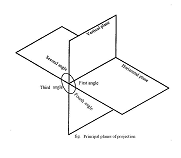
Note: The Second quadrant (angle) and Fourth quadrant (angle) are not used in practice because their views may overlap.
Evaluation Questions
1. Explain what is meant by orthographic projection.
2. Mention three types of plane of projection.
Types of orthographic projection
 First angle orthographic projection:
In first angle projection, the object to be projected is assumed to be placed on the first quadrant (angle) and parallel projectors normal to the planes are used to obtain the views. The view on the vertical plane is the elevation while that on the horizontal plane is called the plan. To know how these views will appear on the drawing paper, the horizontal plane is opened or rebated about the line of intersection of the planes thus placing the “elevation” up and the “plan” down as shown in the figure below. In this situation, the line of intersection otherwise called
 the ground line or XY line or folding line becomes a horizontal plane to the “elevation” and a vertical plane to the plan. The projectors of these views are parallel and normal to the XY line thus satisfying the condition for orthographic projection. See the figure below.
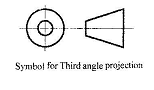
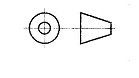
Symbols used in orthographic projection: To know which symbol is used for first angle or third angle orthographic projection, check out for these simple features. The symbol consists of a circle and an object that looks like a truncated triangle . If this truncated triangle comes first before the circle, the symbol is first angle. The reverse is the case for third angle. In other words, the circle represents the direction from which the object is viewed. While the truncated triangle represents the image or view obtained. Objects placed in the first quadrant can only be viewed from the right side when considering the two main principal planes of projection. But objects placed in the third quadrant can only be viewed from the left.
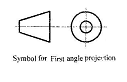 First angle orthographic projection symbol : Here, objects are placed in the first quadrant. Therefore, they are viewed from the right and their images placed to the left (vertical plane) as shown by these illustrations..
Evaluation Questions
-
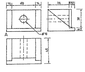
 Draw the figure below in first angle orthographic projection looking at the front elevation in the direction of arrow A
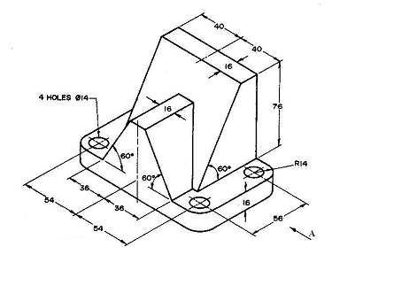
2. Draw full size the fulcrum support shown below in first angle orthographic projection. View the front
elevation in the  direction of A. Show all hidden detail.
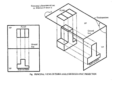 Third angle orthographic projection: In third angle orthographic projection, the object is placed in the third quadrant. Parallel projectors normal to the planes are used to project the elevation on the vertical plane and the plan on the horizontal plane. If the horizontal plane is rebated about the ground line, it is observed that the plan view will appear above the ground line while the elevations will appear below the ground line. See diagram below.
Third angle orthographic projection symbol : Here, objects are placed in the Third quadrant. Therefore, they are viewed from the left and their images placed to the right (vertical plane) as shown by these illustrations.
Evaluation Questions
 1. Draw the figure below in third angle orthographic projection looking at the front elevation in the direction of A
2. Draw the figure below in angle orthographic projection looking at the front elevation in the direction of A

Reading assignment
Engineering drawing 1 by M.A.Parker and F.Pickup pages 43 – 64
Technical drawing by JN Green pages 160 – 171and 184 – 187
Weekend Assignment
Objective
1. Lines in orthographic drawing are projected at angle A. 300 B. 900 C. 1200 D. 3600
2. The two main principal planes of an orthographic projection are A. vertical and horizontal B. parallel and
horizontal C. horizontal and auxiliary D. vertical and auxiliary.
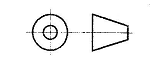 3. The orthographic drawing symbol shown below represents A. first angle B. second angle C. third angle
D. fourth angle.
4. The end view of an object is projected on which of the following planes A. Vertical B. Horizontal.
C. Auxiliary vertical. D. Auxiliary horizontal.
5 The second and fourth angles are not used in orthographic projection because of one of the following reasons.
A. their views are smaller than normal. B. their views are larger than normal. C. their views do not exist.
D. their views may overlap.
Theory
 1. Draw full size the bolster block shown below in first angle orthographic projection
![]() . View the front elevation in the direction of A. Show all hidden detail.
. View the front elevation in the direction of A. Show all hidden detail.
2. Draw full size the fulcrum support shown below in orthographic projection. View the front elevation in the direction of A. Show all hidden detail.
WEEK FOUR-FIVE:
Topic: Conversion of orthographic to isometric.
Content:
(i) Conversion of Orthographic to isometric.
Conversion of objects in orthographic projection to isometric
Method of conversion.
In converting an orthographic view to isometric, the following should be noted.
- The lowest point is the starting point.
- The height of the drawing is derived from the front view and not the plan..
- The width of the drawing is derived from the plan and end views and not the front view.
 Example 1

Method:
(i) Lay out the isometric axes.
(ii) Lay out the overall dimensions, blocking in the size of the object.
(iii) Draw the isometric box enclosing the object.
(iv) Locate other features by measuring along the isometric axes. ie all vertical lines should be drawn parallel to the vertical axis while all other lines should be drawn parallel to the receding axes.
(v) Remove layout lines and darken the remaining lines to complete the drawing.
 Example 2
Method:
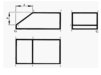
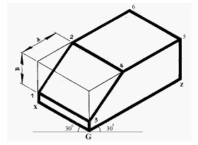
(i) Draw a horizontal line of any convenient length and mark a point G (lowest point) on it.
(ii) From point G, draw a receding line GZ to the right and GX to the left at angle 300 to the horizontal.
(iii)Mark-off lengths G-z and G-x on both receding lines respectively.
(iv)Draw a vertical line z-5 representing the overall height and complete the rectangular box in isometric.
(v)Mark the offsets 5-4, 6-2, G-3 and X-1 on the rectangular block.
(vi)Join 1-3, 2-4, 1-2 and 3-4.
(vii)Use thick continuous line to bring out the shape and clean off unnecessary construction lines.
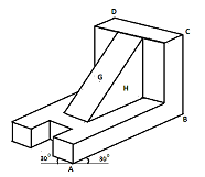
 Example 3. Convert the orthographic drawing shown below to isometric.
Method:
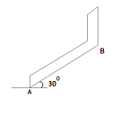
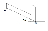
- Draw a horizontal line of a convenient length and mark the lowest point on it.
-

 Choose point A as the lowest point and draw a line from A at an angle of 300 to the horizontal to point B as seen in the given elevation. If B were to be the lowest point, a line would go from point B to the left. See the diagrams below.
- Ensure that all receding lines to the left and right are parallel to each other. The same is applicable to all vertical lines..
- Mark off your dimensions to obtain the isometric drawing.
 Make use of all the given views in order to have a good picture of what is needed. For instance, the part labeled G appears to be at the edge of the front view. But the plan shows it to be at the middle.
Evaluation questions
 1. The figure below shows two views of a Mechanical component in 1ST angle projection. Draw it full size in isometric projection making X the lowest point.
- The figure below shows three views of an engineering component in 1st angle orthographic projection. Draw it full size in isometric. Make point A the lowest.

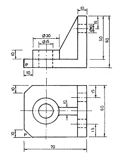
 3. The figure below is two views of a mechanical component shown in 1ST angle projection. Draw it full size in isometric projection . Make P the lowest point.
4. The Figure below shows three views of an engineering block in first angle orthographic projection.
Draw the diagram in isometric. Make A the lowest point.
Reading assignment
Technical drawing by JN Green pages 160 – 171and 184 – 187
Weekend Assignment
Objectives
- The axes of isometric drawing are spaced at an angle of A. 900 B. 1800 C. 1200 D. 1350
- The receding lines of an isometric drawing are drawn at what angle to the horizontal? A. 900 B. 1800 C. 1200 D. 300
- Which of the following orthographic views is used to determine the height of an isometric drawing? A. Plan. B. Front. C. End D. None of the above.
- Which of the following orthographic views is used to determine the width of an isometric drawing? A. Plan. B. Front. C. Section D. None of the above.
- The point from where an isometric drawing is started is called A. highest point.
B. middle point. C. lowest point. D. center point.
Theory
 1. The figure below shows two views of a Mechanical component in 1ST angle projection. Draw it full
size in isometric projection making P the lowest point.
 2. The figure below shows two views of an engineering component. Draw it full size in isometric
projection making A the lowest point.
WEEK SIX-SEVEN:
Topic: Perspective drawing
Content:
- Meaning and types
Perspective drawing
Perspective drawing: This is a pictorial drawing that shows the object as the eyes sees it when looking from a particular point through an imaginary plane called the Picture plane (PP). In Perspective drawing instead of the receding lines remaining parallel as in isometric or oblique drawing, they rather tend to converge at a point called the vanishing point. There are three types of perspective drawing and these are: Parallel or One- point, Angular or Two- point and the Oblique or Three-point perspectives respectively. We shall consider the most common of these (one-point and two point) perspectives in this lesson. Perspective drawing is characterized by the following elements which include: Station Point
(SP), Picture Plane (PP), Ground Line (GL), Horizon Line (HL) and the Vanishing Point (VP).
Station Point: This is the eye of the observer. It is noted on drawings as SP. It is the point from which projectors or the rays from the eyes originate.
Picture Plane: This is the plane directly opposite the observer on which the object is projected. It is noted on drawings as PP.
Ground Line: The ground line is the line of intersection between the ground plane and picture plane. It is noted on drawings as GL.
Horizon Line: This is the line at a distance on which the visual rays from the eyes of the observer meets. It is noted on drawings as HL.
Vanishing Point: this is the point where all receding lines converge on the horizon. It is noted on drawings as VP, VPL or VPR where L or R indicates left or right vanishing point.
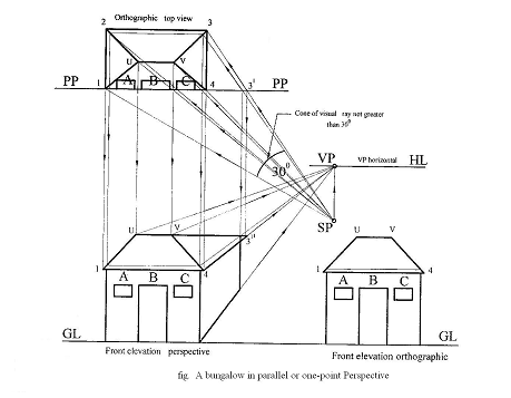 Parallel or One-point Perspective: This drawing is similar to Oblique drawing. The only difference is that the receding lines converge at a point called the vanishing point on the horizon. In practice, one face of the object is placed on the picture plane so that its true shape and size can be accurately drawn. Below is the diagram illustrating a Bungalow building drawn in Parallel or one-point perspective

Method:
(i) Draw the Ground Line GL and layout the front elevation of the Bungalow on it.
(ii) Draw the Picture Plane PP and layout the top orthographic view of the Bungalow on it; showing
the positions of the wall, door and windows as shown in the above diagram.
(iii) Draw the Horizon Line at any convenient distance from the Ground Line.
(iv) Locate the station point SP such that the cone of visual rays will enclose the top view at an angle
not greater than 300.
(v) Draw a vertical line from the station point to meet the horizon in order to locate the vanishing point.
(vi) Draw visual ray lines from the station point to all points on the top view.
(vii) From these points where the visual ray lines meet the top view, drop or project vertical lines downward
towards the ground line.
(viii)Project horizontal lines from the front orthographic view to intersect the vertical lines from the top
orthographic view.
(ix) Project lines from the front perspective view to the vanishing point VP.The intersection of projections lines
from the top view, front orthographic view and the front perspective view gives the required shape of the
Bungalow in one-point perspective drawing.
 Angular or Two-point Perspective: Angular or Two-point perspective drawing is similar to axonometric projection whose complementary angles are 450 and 450 or 300 and 600 as its principal axes. The only difference is that the receding lines of the angular perspective converge at two vanishing points located on the horizon. Below is the diagram illustrating a Bungalow building drawn in Angular or two-point perspective.
Method:
(i) Draw the Ground Line, the Horizon Line and the Picture Plane.
(ii) Draw the front orthographic view on the Ground Line.
(iii) Draw the top orthographic view on the Picture Plane at variable angles preferably 300 and mark the
position of the wall, windows and door on it as show in the figure.
(iv) Locate the Station Point at a distance twice the width of the building and drop a perpendicular from the
edge as shown in the top orthographic view.
(v) Locate the two vanishing points by first drawing lines from the Station Point to the Picture Plane such that
they are parallel to the edge lines of the top orthographic view of the building.
(vi) Draw perpendiculars from the Picture Plane line to the Horizon and this will give the two vanishing points
VPL and VPR.
(vii) Draw the visual ray lines from the station point to all the top points in the top orthographic view
as shown by the arrow heads.
(viii) Extend vertical lines downward from the bottom point of the top orthographic view as well as where the
visual ray lines intersect the Picture Plane line.
(ix) Project horizontal lines from the front orthographic view to intersect the vertical lines from the
top orthographic view.
(x) Project lines from the front perspective view to the vanishing points VPL and VPR. The intersection of
projection lines from the top view, front orthographic view and the front perspective view will give the
required shape of the Bungalow in Two-point perspective drawing.
Evaluation Questions
1. Explain the following types of perspective drawing. (a) Parallel or one- point. (b) Angular or two-points
2. Draw a bungalow in parallel perspective. Use suitable dimensions.
General Evaluation/Revision Questions
1. State 6 dimensioning techniques.
2. Classify the following tools : Hammer, File, Chisel, A pair of dividers, Protractor, A pair of odd-
leg calipers, Vernier Caliper, Scriber, Saw, Centre punch, Screw driver, Surface plate, Spanner,
Steel rule, T- square, Tri-square into (i) Marking out tools (ii) Cutting tools
(iii) Driving tools (iv) Measuring tools.
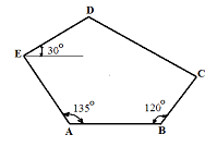 3. An irregular polygon is shown in the figure below.
AB = 70
BC = 40
DE = 75
AE = 80
(a) Construct
(i) the pentagon;
(ii) a square equal in area to the given pentagon.
(b) Draw and state the length of a diagonal of the square in (a)(ii) above.
Reading assignment
Engineering drawing 1 by M.A.Parker and F.Pickup pages 43 – 64
Weekend Assignment
Objective
1. The type of pictorial drawing in which one of the receding axis is drawn at right angle is called ——-
A. isometric. B. oblique. C. perspective D. axonometric.
2. Which of the following types of oblique projection has its receding axis drawn full length? ——-
A. cabinet B. cavalier C. Oblique D. offset.
3. Vanishing point is the characteristics of which of the following types of pictorial drawing?——-
A. isometric B. perspective C. oblique D. axonometric.
4. Which of the following pairs are types of perspective drawing?———- A. parallel and angular
B. ordinate and grid C. vertical and horizontal D. pictorial and orthographic.
5. The receding lines of an isometric drawing are drawn at what angle to the horizontal? A. 600 B. 450 C. 300
D. 900
Theory
 1. Draw the block shown below in Parallel perspective. Use suitable dimensions
2. Draw full size in isometric projection the object shown below.
WEEK EIGHT:
Topic: Auxiliary views
Content:
(i) Meaning of auxiliary projection.
(ii) Auxiliary projection of prisms
(iii) Auxiliary projection of cones.
Meaning of auxiliary projection.
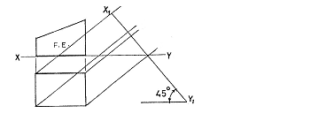
Auxiliary projection: The normal principal planes of projection; the vertical plane VP and the horizontal plane HP used in orthographic projection do not sometimes provide or show sufficient information about parts with inclined or sloppy surfaces. It is therefore important to form another plane which is parallel to these inclined surfaces in order to obtain their true shapes and sizes. The planes of projection and the direction of view used in this case are called the auxiliary planes of projection.
Note: The auxiliary view obtained from the normal front elevation is called “first auxiliary plan” while that obtained from the normal plan is called “first auxiliary elevation”. Other auxiliary views obtained from the first auxiliary views are called “second auxiliary views. See figure below for illustration of auxiliary views.

Rules for drawing an auxiliary plan.
(i) Draw the given normal elevation and normal plan taking note of the direction of view which may either be
shown by an arrow such as K or the inclination of the ground line at an angle.
(ii) Draw a ground or datum line X1-Y1 at any convenient distance from the elevation and at right angle to the
direction of view of arrow K.
(iii) Project lines from all the corners of the normal elevation at right angle to the new ground line X1-Y1. Note
that the corners that are visible to the eyes are represented in solid lines while those that are not visible to the
eyes are drawn with short dashes.
(iv) Transfer distances from the normal plan to locate the shape and size of the first auxiliary plan.
Rules for drawing an auxiliary elevation
(i) Same as the steps for drawing auxiliary plan.
(ii) Draw a ground line X2-Y2 at right angle to the direction of the view ie M.
(iii) Project lines from the corners of the normal plan at right angle to the new ground
line X2-Y2. Visible corners are represented in solid lines while invisible corners are represented in short
dashes.
(iv) Transfer distances from the normal elevation to get the shape and size of the first auxiliary elevation.
Evaluation Questions
1. Distinguish between auxiliary projection and orthographic projection?
2. Explain the following terms: (i) First auxiliary elevation. (ii) First auxiliary plan.
Auxiliary projection of prisms
Note: Prisms are named based on the shape of their bases which could either be square, triangular or
 rectangular.
Example: Draw the auxiliary views of a right square prism shown below.
To draw the first auxiliary plan – project lines from elevation; transfer distances from plan
Method:
(i) Draw the given normal elevation and normal plan.
(ii) Draw a ground or datum line X1-Y1 using its angle of inclination as shown in the given question.
(iii) Using a setsquare and a ruler, project lines from all the edges of the normal elevation ie P, Q, R and S
perpendicular to the ground line X1-Y1 and produced beyond it.
(iv) Transfer distances from the normal plan and mark them off on each respective projection line from P,Q,R
and S to obtain the corresponding points T1L1,N1M1,N11M11 and T11L11. This is the first auxiliary plan.
To draw the first auxiliary elevation-project lines from plan; transfer distances from elevation
Method:
(i) Draw a new ground line X2-Y2 using its given angle of inclination as shown in the question.
(ii) Using a setsquare and a ruler, project lines from all the edges of the normal plan ie L,M,N and T
perpendicular to the ground line X2-Y2 and produced beyond it.
(iii) Transfer distances from the normal elevation and mark them off on each respective projection line from
L,M,N and T to obtain the corresponding points S1P1,R1Q1,R11Q11 and S11P11. This is the first auxiliary
elevation.
Evaluation Questions
The diagrams below show the normal elevation and plan of a square prism.
 Draw full size the following views: (i) The given views (ii) First auxiliary elevation. (iii) First auxiliary plan.
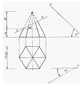
Auxiliary projection of cones
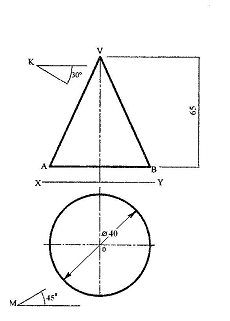
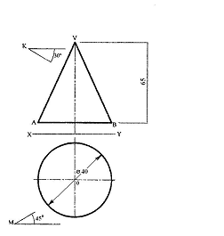
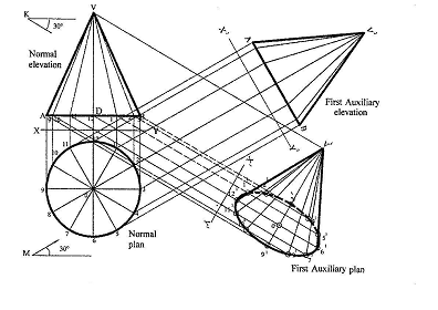 Example: Draw the auxiliary view of a right cone shown below whose vertical height is 60mm and base diameter ф30mm.
To draw the given views
Method:
(i) Draw the given front elevation and plan using the specification provided.
(ii) First, draw a circle of diameter ф30mm and divide it into 12 equal parts.
(iii) Project these divisions upwards to line AB to start the construction of the front elevation. First mark off the
vertical height DV equal to 60mm. Then, radiate points 9, 10, 11, 1, 2, and 3 to point V.
(iv) Indicate the direction of views as given.
To draw the first auxiliary plan – project lines from elevation; transfer distances from plan
Method:
(i) Project lines from points 9,10,11, 12,1, 2 ,3 and V on the normal elevation parallel to the direction of arrow
K.
(ii) Draw a new ground line X1-Y1 at right angle to these projected lines and at any convenient distance from
the elevation.
(iii) Transfer distances from the normal plan and using the ground line as reference line, mark off these
distances on each respective projection line ie points 91, 10181, 11171,121 01 61, 1151, 2141, 31. To locate the
vertex V1, draw a vertical line at 01, perpendicular to line 12-61 and this line cuts the projected line from V
at V1 then radiate lines from V1 to other points to get the first auxiliary plan.
To draw the first auxiliary elevation-project lines from plan; transfer distances from elevation
Method:
(i) Project lines from all the divisions on the circle parallel to the direction of arrow M but perpendicular to a
new ground line X2-Y2 which is drawn at any convenient distance from the normal plan.
(ii) Transfer distances from the normal elevation and using the ground line X2-Y2 as reference line, mark off
these distances on each respective projection line to obtain the first auxiliary elevation.
 Evaluation Questions
The diagram shown below represents the normal elevation and plan of a right cone. Draw full size the following views: (i) The given views (ii) First auxiliary elevation. (iii) First auxiliary plan.
General Evaluation/Revision Questions
1. With the aid of diagrams, state 7 types of line and their uses
2. ABCD is a rectangle. Diagonal AC is 80mm long while length AB is 65mm. Construct the rectangle.
How long is the width of the rectangle?
3. An ellipse has major axis 120mm and minor axis 80mm. (a) Construct the ellipse using: (i) focal point
method. (ii) Concentric circle method. (iii) intersecting line or rectangle method.
(b) Construct a tangent at a point 30mm above the major axis and to the right of the minor axis.
Reading assignment
Technical drawing for school certificate and GCE by J.N. Green pages116 – 122
Weekend Assignment
Objective
1. Which of the following views are relevant measurements taken in drawing the second auxiliary elevation?
A. first auxiliary elevation only. B. First auxiliary elevation and first auxiliary plan. C. Standard elevation
and first auxiliary plan. D. Second auxiliary plan and first auxiliary plan.
2. From which view is the second auxiliary elevation projected? A. First auxiliary elevation.
B. First auxiliary plan. C. Second auxiliary plan. D. Standard elevation.
3. Which of the following is not used when projecting the second auxiliary elevation? A. First auxiliary plan.
B. Normal elevation. C. Normal plan. D. None of the above.

 4. The view labelled q in the diagram above is called A. auxiliary plan. B. end elevation. C. auxiliary elevation. D. front elevation.
5. Which of the following represents the auxiliary view of the casting on X1Y1?
Theory
 The diagram shown below represents the normal elevation and plan of a right cone. Draw full size the following
views: (i) The given views (ii) First auxiliary elevation. (iii) First auxiliary plan.
WEEK NINE:
Topic: Auxiliary views
Content:
(i) Auxiliary projections of cylinders.
(ii) Auxiliary projections of cubes.
(iii) Auxiliary projections of Pyramids.
Auxiliary projection of cylinders
Example: Draw the auxiliary views of a right cylinder of height 50mm and base diameter ф30mm.
To draw the first auxiliary plan ( project lines from elevation; transfer distances from plan)
Method:
(i) Draw the given elevation and plan as follows.
(ii) Divide the plan (circle) into 12 equal parts.
(iii) Project these divisions upwards to the X-Y line and then produced to the bottom and top of the cylinder.
These projected lines meet the bottom of the cylinder at 0,1,2,3,4,5 and 6 and the top at 01,11,21,31,41,51
and 61.
(iv) Project lines from the bottom and top of the cylinder parallel to the direction of view ie arrow A.
(v) Draw a new ground line X1-Y1 at right angle to these projected lines and at any convenient distance from
the elevation.
(vi) Transfer distances from the normal plan and using the ground line X1-Y1 as reference line, mark off
these distances on each respective projection line just as it was done to get the base of the first
auxiliary plan of the cone above. This should be done for the projection lines from both the bottom
and top of the elevation. Then join the points together to finish the first auxiliary plan.
To draw the first auxiliary elevation (project lines from plan; transfer distances from elevation)
Method:
(i) Project lines from all the divisions on the plan (circle) parallel to the direction of arrow B but
perpendicular to a new ground line X2-Y2 which is drawn at any convenient distance from the
normal plan.
(ii) Transfer distances from the normal elevation and using the ground line X2-Y2 as reference line, mark
 off these distances on each respective projection line to obtain the first auxiliary elevation.
Evaluation Questions
The figure below is a cylinder in orthographic projection. Draw the given views and show the following:
 (i) The given views. (ii) First auxiliary plan. (iii) First auxiliary elevation
![]()
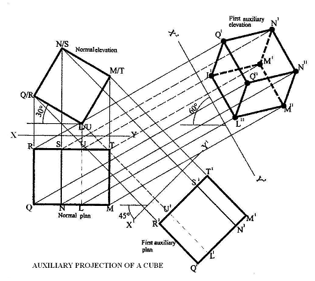
Auxiliary projection of Cubes
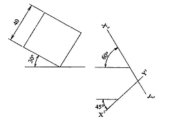
 Example: Draw: (i) The plan (ii) the first auxiliary plan and (iii) the first auxiliary elevation of a cube inclined at
an angle of 300 to the horizontal as shown below.
To draw the first auxiliary plan (project lines from elevation; transfer distances from plan)
Method:
(i) Draw the elevation and plan as follows.
(ii) Using L/U as the lowest point, construct the elevation L/U, M/T, N/S and Q/R inclined at an angle of
300
(iii) Project these points in (ii) downwards to draw the normal plan as seen in the diagram below.
(iv) Project lines from the edges of the normal elevation ie points L/U, M/T, N/S and Q/R perpendicular
to a new ground line X1-Y1 and produced beyond it.
(v) Using X-Y as the reference line, transfer distances from the normal plan and using the ground line
X1-Y1 as reference line, mark off these distances on each respective projection line to get points that
produces the first auxiliary plan.
To draw the first auxiliary elevation-project lines from plan; transfer distances from elevation
Method:
(i) Draw a new ground line X2-Y2 using its given angle of inclination as shown in the question.
(ii) Using a setsquare and a ruler, project lines from all the edges of the normal plan ie points R, S, U ,T
and Q, N, L,M perpendicular to the ground line X2-Y2 and produced beyond it.
(iii) Transfer distances from the normal elevation and mark them off on each respective projection lines
from R, S, U, T which form the top of the cube ie R11, S11, U11,T11 and those from Q, N, L,M which
form the bottom of the cube ie Q11, N11, L11, M11. This is the first auxiliary elevation.
Evaluation Questions
 The figure below is a cube inclined at an angle of 300 to the horizontal. Draw the: (i) plan (ii) the first
auxiliary plan and (iii) the first auxiliary elevation.
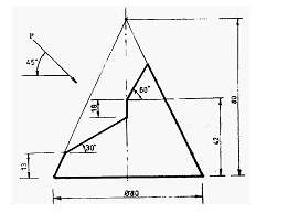
Auxiliary projection of pyramids
Note: Pyramids are named by the shape of their bases which could either
be square, triangular, rectangular, hexagonal etc.
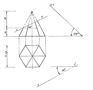
Example: The figure below is a hexagonal pyramid in orthographic projection.
Draw the views and show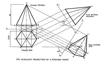 the following: (i) First auxiliary plan. (ii) First auxiliary elevation.
To draw the given views
Method:
(i) Draw a circle of diameter ф35mm and construct a hexagon of sides CEBEDA on it using 600
setsquares.
(ii) Project lines upwards from the edges and centre of the hexagon to line AB.
(iii) Produce the centre line beyond the base and mark off the vertical height OV.
(iv) Radiate lines from A, C/D, O, E/F and B to point V.
(v) Indicate the direction of views as shown in the question.
To draw the first auxiliary plan (project lines from elevation; transfer distances from plan.)
Method:
(i) Project lines from points A, C/D, O, E/F, B and V on the normal elevation perpendicular to the
direction of the ground line X1-Y1 and produced beyond it.
(ii) Using X-Y as reference line, transfer distances from the normal plan and using the ground line X1-Y1
as reference line, mark off these distances on each respective projection line ie points
A1,C1D1,O1,E1F1,B1 and V1. To locate the vertex V1, draw a vertical line at 01, perpendicular to the
centre line O-O1and this line cuts the projected line from V at V1.Then, radiate lines from V1 to
A1,C1,D1,O1,E1,F1,and B1 to get the first auxiliary plan.
To draw the first auxiliary elevation-project lines from plan; transfer distances from elevation
Method:
(i) Project lines from all the edges, A, C, E, B, F, D and the centre O of the normal plan perpendicular to
a new ground line X2-Y2 which is drawn at any convenient distance from the normal plan but
inclined at an angle of 600.
(ii) Transfer distances from the normal elevation and using the ground line X2-Y2 as reference line, mark
off these distances on each respective projection line to obtain the first auxiliary elevation.
Evaluation Questions
 The figure shown below is a hexagonal pyramid in orthographic projection. Draw the: (i) given views (ii) first
auxiliary plan. (iii) first auxiliary elevation.
General Evaluation/Revision Questions
1. Draw title blocks for Architects and Engineers on a plane paper.
2. With the aid of a sketch diagram, explain the difference between datum and chain dimensioning
respectively.
3. The size of your room measures 4m by 6m. Calculate to the nearest whole number, the number of square
tiles of size 30cm that would be needed to finish the tiling work?
4. A point on the circumference of a circle, diameter 70mm, rolls along a straight line without slipping.
(i) Trace the locus of the point as the circle completes one revolution. (ii) Name the locus.
5. Draw diagrams to show the following butt joints. (i) Single- V butt . (ii) Double- J butt.
(iii) Single-bevel butt.
Reading assignment
Technical drawing for school certificate and GCE by J.N. Green pages116 – 122
Weekend Assignment
Objective
1. An auxiliary view that is projected from the first auxiliary elevation is called? A. First auxiliary
plan. B. Second auxiliary elevation. C. Second auxiliary plan. D. First auxiliary elevation.
2. From which views are relevant measurement taken in drawing the second auxiliary elevation?
A. First auxiliary elevation only. B. First auxiliary elevation and first auxiliary plan.
C. Second auxiliary plan and first auxiliary plan. D. Standard elevation.
3. An auxiliary view projected from a normal elevation is called? A. First auxiliary elevation.
B. Auxiliary plan. C. Auxiliary elevation. D. First auxiliary plan.
4. A view which is drawn on a plane other than the normal principal planes of projection is called?
A. Oblique. B. Isometric. C. Auxiliary. D. Orthographic.
5. An auxiliary view projected from a normal plan is called? A. Auxiliary plan. B. First auxiliary plan.
C. Auxiliary elevation. D. First auxiliary elevation.
Theory
1. The figure 1 shown below is a hexagonal pyramid in orthographic projection. Draw the: (i) given
![]() views (ii) first auxiliary plan. (iii) first auxiliary elevation.
views (ii) first auxiliary plan. (iii) first auxiliary elevation.
2. The figure below shows a frustum of a right cone. Draw the: (i) given elevation (ii) complete orthographic
 plan (iii) complete auxiliary plan viewed in the direction of arrow P.
WEEK NINE:
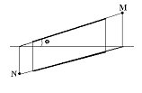
Topic: Lines in space
![]() Content:
Content:
(i) Meaning of traces and the true length of a line.
(ii) Methods of determining the true length and inclination of lines in space.
.Meaning of traces and the true length of a line.
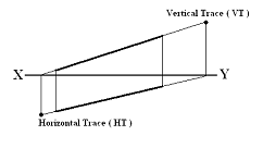
Trace: A line inclined to a normal principal plane of projection would if produced penetrates this plane. The point where this happens is called a trace. The true or actual
length is the length of this inclined line obtained when it is projected on an auxiliary plane parallel to it.
Methods of determining the true length and inclination of a line in space.
1. Auxiliary method: This method is the same as that used in auxiliary projection of inclined surfaces of objects treated earlier on.
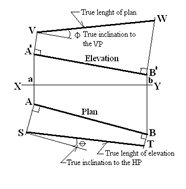 Example 1: Determine the true length and angle of inclination of a line AB inclined in space as shown in figure below.
Method:
(i) Draw the X-Y line.
(ii) Draw the plan AB and the elevation A1B1 of the line.
(iii) Draw the projection lines AA1 and BB1.
(iv) To obtain the true length of the normal plan AB, project lines at right angle from the ends A1 and B1 of the normal elevation and using line X-Y as the reference line, transfer the distances aA and bB of the normal plan and mark them off respectively to locate points V on the perpendicular line from A1 and W on the perpendicular line from B1. Line VW is the true length of the plan and it is inclined to the vertical plane VP at an angle ф
(v) To obtain the true length of the normal elevation A1B1, project lines at right angle from the ends A and B of the normal plan and using line X-Y as the reference line, transfer the distances aA1 and bB1 of the normal elevation and mark them off respectively to locate points S on the perpendicular line from A and T on the perpendicular line from B. Line ST is the true length of the elevation and it is inclined to the horizontal plane HP at an angle Ө.
2. Rebatment or revolution method:
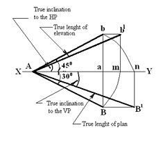 Example 1: Consider an oblique line AB which is inclined at an angle of 300 to the vertical plane and 450 to the horizontal plane.
Method:
(i) Draw the usual X-Y line.
(ii) Draw the plan and elevation of line AB.
(iii) Draw a line to connect the elevation and plan i.e. line bB.
To draw the true length TL of the elevation Aa and its true angle of inclination to the horizontal plane HP.
(iv) With a pair of compasses pin at point A and radius AB, swing an arc to meet the X-Y line at point
m and then project a vertical line upwards from this point.
(v) Take the distance ab and mark it off on this line to get point b1.
(vi) Draw a horizontal line to connect b to b1. Line Ab1 is the true length TL of the elevation and its
angle of inclination to the horizontal plane HP is measured.
To draw the true length TL of the plan AB and its true angle of inclination to the vertical plane VP.
(vii) With A as centre and radius Ab, swing an arc to meet the X-Y line at point n and then project a
vertical line downwards from this point.
(viii)Take the distance aB and mark it off on this line from point m to get point B1.
(ix) Draw a horizontal line to connect B to B1. Line AB1 is the true length of the plan and its true angle
of inclination to the vertical plane VP is measured.
Determination of the true shape of a triangular lamina
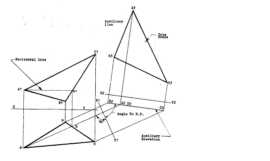
Method
- Draw the given elevation and plan of the lamina with the ground line X-Y drawn between them.
- Determine point D on the plan by drawing a horizontal line parallel to the ground line X-Y from point A1 to D1 then draw a line vertically down to point D.
- Project a line from point A through D to a convenient point. Similarly, project lines from points B and C parallel to AD produced.
- Draw a ground line X1-Y1 perpendicular to the projected lines from the plan.
- Obtain distances from X-Y line to points A1,B1 and C1 on the elevation and transfer them, now from X1-Y1 respectively to obtain the auxiliary elevation line B2, A2D2 and C2.
- Similarly, obtain distances from the X1-Y1 to points A,B,C and D on the plan and transfer them to obtain the auxiliary plan A3, B3, C3 now using X2-Y2 as the ground line..
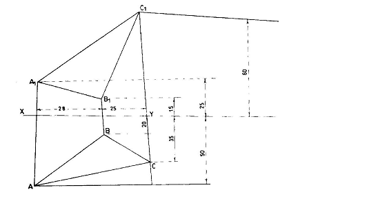
Evaluation question
The figure shown below is the elevation and plan of a triangular lamina in first angle projection.
- Draw the true shape of the lamina
- Measure and state the
- Angle of inclination to the horizontal plane
- True length of AC.
- Indicate on the drawing, the;
- auxiliary elevation;
- auxiliary plan.
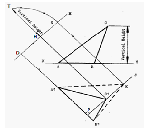 Determination of the true shape of a triangular lamina having one of its faces resting on the horizontal line.
Method
- Draw the elevation and plan of the lamina with the face AB lying on the horizontal plane.
- Draw B1A1 produced to a convenient point D.
- Erect a perpendicular DE at point D.
- Draw a line from C1T parallel to B1D and mark off the vertical height HT on this line.
- With a compass pin at point H and radius HT, swing an arc to meet DE at G.
- Draw a line from G parallel to HC1 and this intersect the altitude PC1 produced at point K.
- Join KA1 and KB1
Evaluation Questions
1. Determine the true length and angle of inclination of the elevation a1b1 and plan a2b2 inclined in space as shown in figure below using the auxiliary method.

 2. The figure below shows the diagonal of a cube inclined at 450 to both the horizontal and vertical planes. Use rebatment method to obtain the true length and inclination of the diagonal.
Reading assignment
Technical drawing for school certificate and GCE by J.N. Green pages 123-130.
Engineering drawing 1 by M.A.Parker and F.Pickup pages 138 – 148.
Engineering drawing 2 by M.A.Parker and F.Pickup pages 204 – 230.
Weekend Assignment
Objective
1. Which of the following is not a method used to determine the true length of a straight line?
A. 4-center method. B. auxiliary method. C. revolution method. D. rebatment method.
 2. The point at which a line in space, if produced, penetrates a plane is called? A. seam. B. joint line.
C. trace. D. datum.
Use the figure below to answer questions 3-5
3. The point N on the diagram above is called? A. seam. B. vanishing point. C. focal point.
D. horizontal trace.
4. The point M on the diagram above is called? A. vanishing point. B. seam. C. horizontal trace.
D. vertical trace.
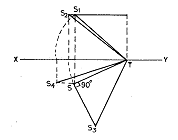 5. The true length of the oblique line ST in the diagram below is A. SS4 B. S2T C. S1T. D. SS3
Theory
1. The elevation of a line AB is of length 60mm and its plan is 45mm. If the elevation is inclined at an

angle of 450 to the X-Y line. Draw the true length of the plan and elevation and their true inclinations.
2. The figure above shows the plan and elevation of a straight line. The line is inclined to both the
horizontal and vertical planes.
Determine:
(a) the true length of the line.
(b) the true angle of inclination to both planes
WEEK ELEVEN:
Topic:
Introduction to building drawing.
![]()
![]()
Content:
(i) Meaning of working drawing.
(ii) Examples of working drawing.
Meaning of working drawing.
Working drawing is a type of architectural or mechanical drawing from which construction work is actually carried out. Therefore, they must give all the graphical information necessary for constructional purposes and must be accurately drawn in orthographic projection showing the plan, elevations and essential sections. There are working drawings for mechanical components, site plan, foundation plan, floor plan and elevations. They must have detailed dimensioning, appropriate titles and the scale used.
Evaluation
1. Define a working drawing.
2. Mention some of the features of a working drawing.
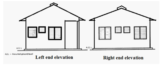
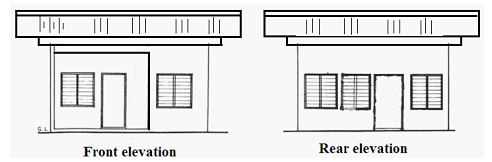
 Example of the working drawing of a bungalow.
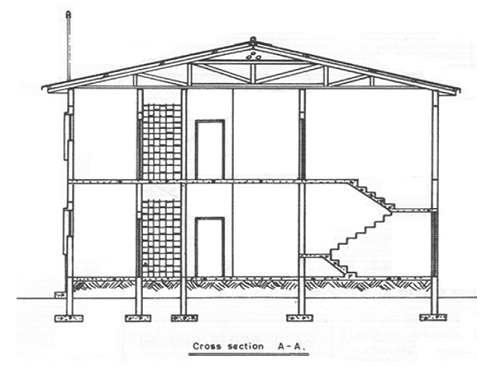
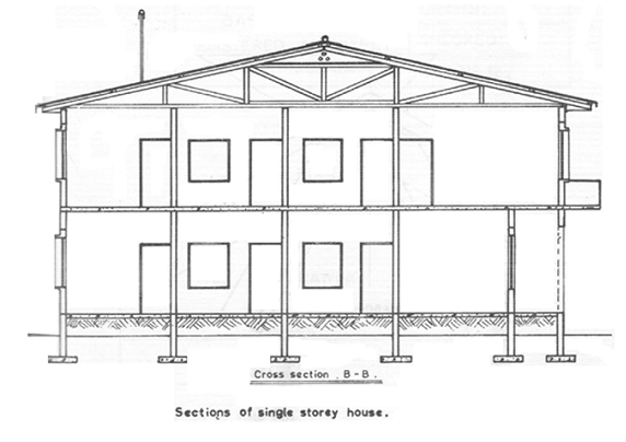
 Example of the working drawing of a storey building.
Evaluations
1. Draw a floor plan of your dream bungalow building.
2. Sketch the front, end and rear elevations of your school building.
Reading assignment
Visit www.google.com for types of working drawings.
Drafting technology by Spence pages 687 – 704.
Weekend Assignment
Objective![]()
1. On a building floor plan, the symbol above represents A. window. B. lintel. C. door. D. column.
 2. In a building floor plan. the part shown below can be identified as a A. lintel B. door. C. window.
D. Arch
3. Which of the following can be found in a door opening? A. Sill. B. Jamb. C. Eaves D. Tread.
4. A function of an internal wall is to A. carry loads. B. divide the space. C. enhance wall stability.
D. reinforce the foundation.
5. Which of the following is not a roof member? A. Muntin. B. Ridge. C. Purlin. D. Rafter.
Theory
1. Mention 5 characteristics of a working drawing.
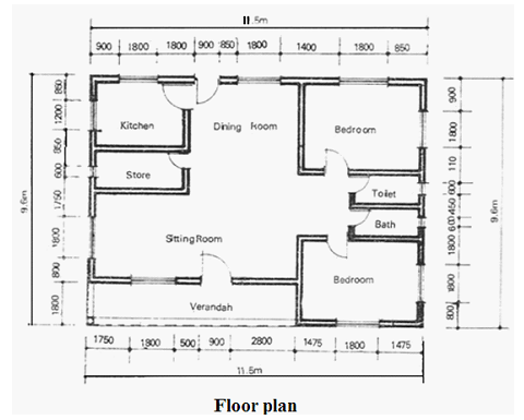
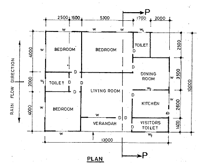 2. The figure below shows the sketch plan of a three bedroom bungalow. Study the given specifications and answer the following questions.
SPECIFICTIONS
Foundation: 800 X 225 strip laid 1000 below ground level.
Wall: All walls are 225 thick sandcrete, hollow blocks, with 13 mortar rendering on both sides.
Floor: 300 hardcore; 150 thick concrete slab; 25 mortar screed.
Finished floor to ceiling, 3000.
Doors: Main entrance – 2100 X 1800 flush wooden in 120 X 80 timber frame.
Inside – 900 X 210 X 40 flush wooden in 100 X 50 timber frame.
Kitchen (outside) – 900 X 2100 fabricated metal in 100 X 50 metal frame’
Windows: All glass louvred with aluminum carriers in 100 X 50 timber frames.
Toilets (W1) – 800 X 500.
Others – 1400 X 1200.
Lintel: 225 X 255 reinforced concrete.
Roof: Pitch angle 120 (gable roof) with corrugated aluminum sheets; 300 eaves projection;
timber rafter 200 X 50 at 1000 centres; purlins 75 X 50 at 900 centres;
ceiling joist 50 X 50 at 1200 centres.
Note: (Assume suitable dimensions where necessary)
Draw the:
(a) floor plan of the building to a scale of 1 : 100;
(b) front elevation of the building to a scale of 1 : 100;
(c) sectional elevation P – P of the building to a scale of 1 : 50.