Share this:
FIRST TERM E-LEARNING NOTE
SUBJECT: TECHNICAL DRAWING CLASS:SS2
WEEK TOPIC
1. Revision of Isometric Circles.
2-4. Loci: Archimedean Spiral,Helix,Hyperbola and Link Mechanisms.
5. SurfaceDevelopmentof Oblique Pyramids, Cones.
6-8. SurfaceDevelopment Interpenetration
9. Pictorial Views (Drawings).
10-11.PictorialDrawing.
REFERENCE MATERIAL
- Technical Drawing by J.N. Green
- Engineering Drawing 1 by M.A.Parker and F.Pickup
- Metal Work Technology by G.H. Thomas.
- Drafting Technology and Practice by William P. Spence
- www.google.com
- Technical Drawing for Senior Secondary schools by Y.A Thanni and C.A Faseun-MoteshoPages 97-103
WEEK ONE
REVISION OF ISOMETRIC CIRCLES
CONTENT
- Construction of isometric circles
Circles, Arcs and Curves in Isometric
Circles in isometric:Circle in isometric form appears like an ellipse. There are different methods of drawing a circle in isometric projection and these include: Four-centered approximate ellipse, ordinate or grid and offset methods.
Four-centered approximate ellipse method
![]() For instance, to draw a circle of diameter 2cm in isometric using the four-centered method, follow the procedures below:
For instance, to draw a circle of diameter 2cm in isometric using the four-centered method, follow the procedures below:
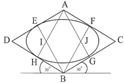
Fig. Four-centre method
Method:
- Draw a square in isometric equal in size to the diameter of the given circle. Bisect each side.
- From point A, draw lines to meet the mid-points of line BD and BC at H and G respectively.
- Repeat the procedure in (iii) with point B to get points E and F respectively.
- The point of intersection of these lines i.e. I and J are centers of arc.
- With I as center and radius IE or IF, draw an arc EH. Repeat same with center J to draw arc FG.
- With A and B as centers draw arcs GH and EF respectively to complete the circle.
Ordinate or Grid Method
![]()
![]() For instance, to draw a circle of diameter 2cm in isometric using the ordinate or grid method, follow the procedures below:
For instance, to draw a circle of diameter 2cm in isometric using the ordinate or grid method, follow the procedures below:
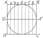
Normal circleIsometric circle
Method:
- Construct a square A1B1C1D1 of same diameter to enclose the given circle in orthographic.
- Draw a line E1F1 as the horizontal diameter of the circle.
- Divide the square into any number of equal parts called ordinate or grid i.e. a, b, c, d, e, f andgas the case may be. Take note of the distances of the points where each grid cuts the circle.
- Construct a square A1B1C1D1 of same diameter in isometric and repeat exactly the same division asdone the plane square on it.
- Transfer distances along each grid of the normal square to its corresponding grid of the isometric square.
The positions of these distances mark out the circle in isometric. See figures above.
Offset method
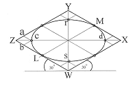
 For instance, to draw a circle of diameter 2cm in isometric using the offset method, follow the procedures below:
Normal circle Isometric circle
Method:
- Construct a square WXYZ of equal size as the given circle to enclose it.
- Determine the mid points L, Q, M and P of the square.
- Draw diagonals WY and XZ.
- Determine the points c, r, d and s where the diagonals cut the circle.
- Draw a square in isometric of same size as the square in (i)
- Repeat steps (ii) and (iii).
- Transfer the lengths Z-a and Z-b of the plane square to the isometric square to get point c.
Use same method for points r, d, and s respectively.
- Join points c, P, r, M, d, Q, s and L to get the circle in isometric form.
![]() Drawing of Arcs in Isometric:The method of drawing arcs in isometric is the same as the four– centered method of drawing circles. Here, it is not necessary to draw the entire isometric square since an arc is only a part of circle.
Drawing of Arcs in Isometric:The method of drawing arcs in isometric is the same as the four– centered method of drawing circles. Here, it is not necessary to draw the entire isometric square since an arc is only a part of circle.

Method:
- From the corner A where the arc is to be drawn, lay off the radius r of the arc equally on bothedges.
- From each of these points P and Q respectively, draw perpendicular lines
- The point of intersection u of these perpendicular lines marks the center of the arc to bedrawn. With u as center and radiusuP or uQ draw the required arc PQ.
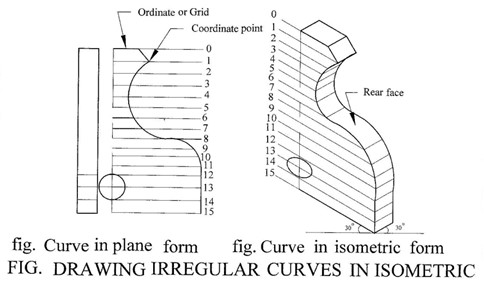
Drawing of Irregular Curves in Isometric: The ordinate or grid method of drawing circles in isometric is appropriate for this purpose. This is done by drawing lines or ordinates at equal spacing on the orthographic view of the object to the same scale as the isometric. Distances are then transferred with a divider on the isometric axis of the object to be drawn. See the figures below for more illustration.

Method:
(i) Draw a series of equally spaced parallel lines (ordinates) on the given plane view.
(ii) Where each ordinate line intersects the curve forms a coordinate point.
(iii) Draw an isometric axes of the same dimensions as the given plane view.
(iv) Repeat step (i) on the drawn isometric axes.
(v) With a pair of dividers, transfer the coordinates of the plane view to the isometric view. The rear faceie the thicknessis drawn the same way.
Evaluation
- Construction the following isometric circles:
- radius 40mm,
- diameter 60mm
- radius 50mm.
General Evaluation
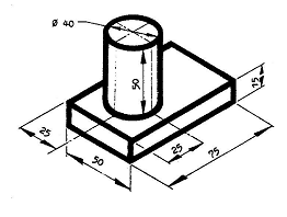
1. Draw full size in isometric projection the pivot block shown below.

 2. Draw full size in isometric projection the object shown below.
(i). Draw a bungalow in parallel perspective. Choose your own dimensions.
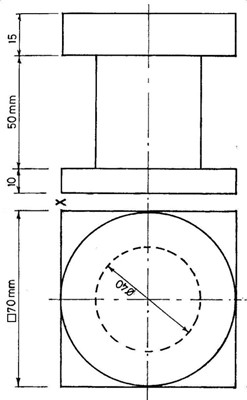
 3. The figure below shows two views of a Mechanical component in 1ST angle projection. Draw full size in isometric projection this views making X the lowest point.
READING ASSIGNMENT
Drafting technology and practice by William P. Spence. Pages 394 – 408
Engineering drawing 1 by M.A.Parker and F.Pickup pages 43 – 64
WEEKEND ASSIGNMENT
- Square in isometric projection has the shape of A. rectangle B. kite C. rhombus. D. hyperbola.
- Circles in isometric projection has the shape of A. rectangle B. parabola C. ellipse. D. hyperbola.
- The type of pictorial drawing in which two of the receding axis is drawn at 45 degree to the horizontal is called A. isometric. B. oblique. C. perspective D. axonometric.
- Which of the following is not a method of drawing isometric cicles. A. four-centered approximate ellipse B. ordinate or grid C. offset methods. D. Conic method
- The type of pictorial drawing in which two of the receding axis is drawn at 30 degree to the horizontal is called A. isometric. B. oblique. C. perspective D. axonometric.
THEORY
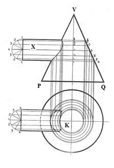
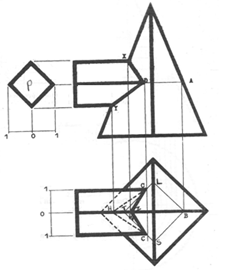
 1.The figure below shows three views of an engineering component in 1st angle orthographicprojection. Draw full size inisometric,theseviews. Make point A the lowest.

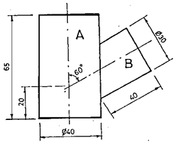
2. The figure below shows two views of a Mechanical component in 1ST angle projection. Draw full
 size in isometric projection this views making P the lowest point.

![]() WEEK TWO, THREE AND FOUR
WEEK TWO, THREE AND FOUR
TOPIC: LOCI
CONTENT
- Archimedean Spiral
- Hyperbola
- helix
- Link mechanisms
Construction of Archimedean Spirals
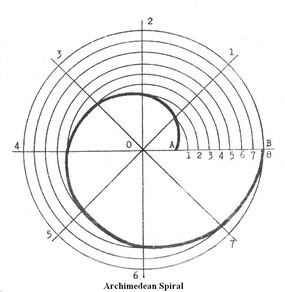
Spiral: An Archimedean spiral is the locus of a point moving uniformly along a straight line rotating about a fixed point at an even speed.
![]() To draw an Archimedean spiral when given the Pole, the Longest and Shortest Radii.
To draw an Archimedean spiral when given the Pole, the Longest and Shortest Radii.
Method:
- Draw a vertical and horizontal line.
- Mark the pole O, the shortest radii OA and the longest radii OB.
- With O as centre and radius OB, draw a circle and divide it into 8 equal parts. Join the points together to point O.
- Divide AB into the same number of equal parts.
- With O as centre and radius O1, draw an arc to cut the radial line from 1.
- Repeat the same for 2, 3, 4….8. Draw a curve through these points to obtain the curve.
Application
(i) The principles of spirals are used in the construction of hair spring of clocks and wrist watches.
Evaluations
1. Define Archimedian spiral.
2. An Archimedian spiral has a shorter and longer radii of 30mm and 80mm respectively. Construct the spiral.
Construction of Hyperbolas
Hyperbola: The Hyperbola is the locus of a point that moves so that the ratio of its distances from the Focus and Directrix (eccentricity) is constant and is greater than unity (> 1). Lines which are tangent to the Hyperbola at infinity are called asymptotes
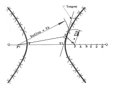 To construct a Hyperbola when given the foci and the transverse Axis
Method:
- Draw a straight line Q-Q of any convenient length and locate the positions of the given foci F and F1, and the transverse axis VV1 on it.
- From the focal point F, mark off any convenient number of equal units to the right to get points A, B, C, D, E, etc.
- With F1 as centre and radius VA, draw an arc above and below the transverse axis. Then with F as centre and radius V1A, draw arcs to cut the previous ones as shown in the diagram above.
(iv) Repeat the same procedure with B, C, D, etc and join the points of intersection to obtain the curve.
To draw the hyperbolic curve for a given ratio, say 3/2

Method:
- Locate the positions of the focus, F and directrix.
- Divide GF into five equal parts ( 3 plus 2 ).
- Locate the position of the vertex, V such that V will be two divisions from G.
- Draw a line AA parallel to the directrix. With F as centre and radius GH times the eccentricity, draw arcs to cut AA above and below the axis. These are points on the curve.
- Repeat same procedure to get more points on the curve.
Note: The distance GH should be chosen such that the radius from the focus is easily calculated.
To construct a hyperbola when given the Ordinate, the Vertex and the Transverse Axis

Method:
(i) Indicate point O and mark the ordinate each side of O, ie OA and OB.
(ii) Construct a rectangle on the given ordinate.
(iii) Draw a perpendicular from point O and indicate on it the vertex V and transverse axis VV1.
(vi) Divide OA, OB and the two perpendiculars at A and B into the same number of equal parts. Radiate lines from the vertex V to each division on both perpendiculars at A and B respectively. Also, from the transverse axis V1, radiate lines to each division on OA and OB. Where corresponding divisions intersect give the hyperbolic curve.
Evaluation
1.A hyperbola has its vertex 12mm from its directrix and its focus 20mm from the vertex. Draw the locus using the locus method.
2.Draw a rectangular hyperbola having a point on the curve 18 mm from the vertical asymptote and 76mm from the horizontal asymptote.
General Evaluation Questions
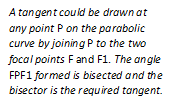
1. An ellipse has major axis 120mm and minor axis 80mm. (a) Construct the ellipse using the focal point method. (b) Construct a tangent at a point 30mm above the major axis and to the right of the minor axis.
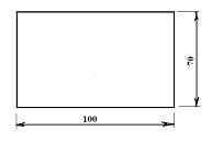 2. The two sides of the rectangle below represent the major and minor axes of an ellipse respectively.
(a) Using rectangular method construct the ellipse; (b) Construct a tangent to the ellipse at a point 20mmvertically above the major axis and on the right of the minor axis.
3. Construct a parabola whose span is 90mm and height 60mm using the circumscribing rectangle method.
Construct a tangent on it at a point 50mm above the span and to the left.
4. A hyperbola has its ordinates as 70mm by 40mm and a transverse axis of 60mm. Construct the hyperbola.
5. Using the parabolic envelope method, construct a parabola whose span and height are respectively 90mm and 80mm.
READING ASSIGNMENT
Technical drawing by JN Green.Pages 55-57, 141-143.
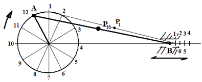
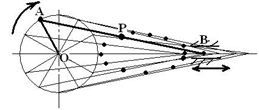
Link mechanism: In a link mechanism, a member called the crank has a connecting rod attached to it by a pin joint. As the crank rotates through one revolution, the connecting rod is therefore made to move in a specified direction. A point on the connecting rod traces out a path as the crank rotates. The mechanism is drawn in several positions and the new position of the point marked. The principle of link mechanism makes it possible to determine the forces present in a mechanical system.
Method:
(i) Draw a circle to represent the movement of the crank if it is to rotate through 1 revolution and divide it into12 equal parts
(ii) Locate the initial positions of the crank and connecting rod and construct them just exactly the way they appear on the given question having studied the dimensions.
(iii) Identify the direction of movement of the crank. For instance the case above is clockwise and this implies that the crank will move from the starting point A to 1, 2, 3,……A while the connecting rod will experience a corresponding linear displacement along the centre line.
![]() (iv) The position of point P on the connecting rod at each position of the crank’s rotation is marked ie P1 for A1and so on. See figure below.
(iv) The position of point P on the connecting rod at each position of the crank’s rotation is marked ie P1 for A1and so on. See figure below.
![]() Evaluation Questions
Evaluation Questions
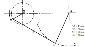
![]() 1. The figure below shows a crank OA which revolves about a centre O, and a crank BD which oscillates along the arc EC. The link AD is connected to the crank as shown. Plot the locus of the mid point P for one revolution of the crank OA.
1. The figure below shows a crank OA which revolves about a centre O, and a crank BD which oscillates along the arc EC. The link AD is connected to the crank as shown. Plot the locus of the mid point P for one revolution of the crank OA.
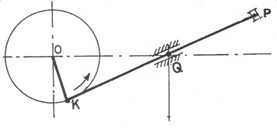
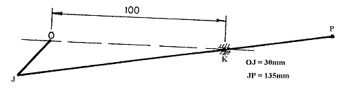 2. The figure below shows a slider crank mechanism. Link JP is driven by a crank OJ, and it is constrained to pass through a pivot at K. Plot the locus of the end point P when OJ makes one revolution.
![]() 3. A crank mechanism is shown below, OA revolves clockwise about O at a constant speed, and the end B of
3. A crank mechanism is shown below, OA revolves clockwise about O at a constant speed, and the end B of ![]() the rod AB is constrained to move along PQ. Plot the locus of point R for one complete revolution of the crank.
the rod AB is constrained to move along PQ. Plot the locus of point R for one complete revolution of the crank.
![]() 4. The figure above shows a crank OA of a link mechanism which rotates clockwise at constant speed about O. During each revolution, the point E slides to and fro along CD. Draw full size the locus of point B for one revolution of OA.
4. The figure above shows a crank OA of a link mechanism which rotates clockwise at constant speed about O. During each revolution, the point E slides to and fro along CD. Draw full size the locus of point B for one revolution of OA.

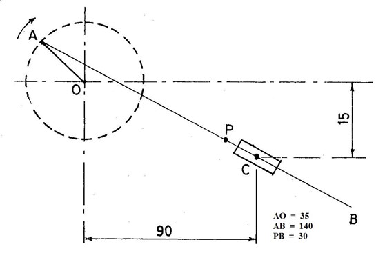
5. In the link mechanism below, OA revolves clockwise about O, while AB slides through the pivoted block C. Draw the locus of point P on the link mechanism for one revolution.

6. The diagram below shows a simple crank mechanism. The crank OA rotates anti-clockwise, the connecting rod AP is pinned to crank OA at the end A, and end P is constrained to slide along the path QR. Draw the locus of the mid-point N for one revolution of the crank. OA = 25mm and AP = 85mm.

 7. In the crank mechanism shown below, AB oscillates as the crank CD rotates about D. Construct the locus of point P for a complete revolution of crank CD.
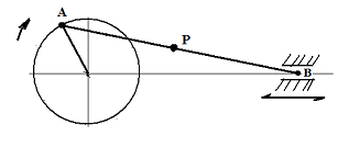
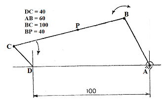
8. The diagram below shows a link mechanism. The crank OB rotates about a centre O in an anti-clockwise direction. It is also pin jointed to a rod CA at point B. The rod is constrained to slide through point A. The lengths OB = 25, AB = 100 and BC = 30.
(i) Trace the locus of point C for a complete revolution of OB.
 (ii) What is the name of the shape that the locus traced?
READING ASSIGNMENT
Technical drawing by JN Green page 135.
Engineering drawing by Pickup and Packer pages 37- 42.
WEEKEND ASSIGNMENT
1.If the crank OK in the diagram below moves anticlockwise, the link KP will A. rotate at Q. B. slide towards K.![]() C.slide towards P.D.remain stationary.
C.slide towards P.D.remain stationary.
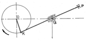
![]() 2.If the crank OK in the diagram below moves clockwise, the link KP will A. rotate at Q. B. slide towards K. C.slide towards P.D.remain stationary.
2.If the crank OK in the diagram below moves clockwise, the link KP will A. rotate at Q. B. slide towards K. C.slide towards P.D.remain stationary.
 3. The shape of the locus shown below is a/an A. circle. B. ellipse.C.cycloid. D. involute.
 4.The locus of points equidistance from two unequal circles is a/an A. straight line. B. curved line. C. ellipse. D. circle.
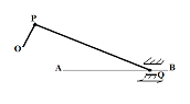
5. Which of the following is true of the link mechanism shown above as the crank OP rotates through one revolution either clockwise or anti-clockwise? A. The connecting rod moves in the direction AB.
B. The connecting rod moves in the direction BA. C. The connecting rod moves through a fixed point Q.
D. Theconnecting rod moves to and fro along line AB.
THEORY
![]() 1. The figure below shows diagrammatically a pair of folding doors. Plot the locus of P for the full movement of A from D to C. AB and BC are each 75 and AP is 30
1. The figure below shows diagrammatically a pair of folding doors. Plot the locus of P for the full movement of A from D to C. AB and BC are each 75 and AP is 30

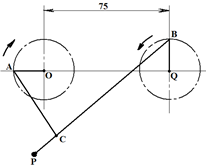
![]() 2. In the given mechanism, the cranks AO and BQ revolve in opposite direction at the same speed, and are joined by the rods AC and BCP. Plot the locus of P for one revolution of the cranks, if AO and BQ are 25mm, AC is 65, BC is 125mm and CP is 20mm.
2. In the given mechanism, the cranks AO and BQ revolve in opposite direction at the same speed, and are joined by the rods AC and BCP. Plot the locus of P for one revolution of the cranks, if AO and BQ are 25mm, AC is 65, BC is 125mm and CP is 20mm.
WEEK FIVE
SURFACE DEVELOPMENT: INTERPENETRATION
CONTENT
- Development of an Oblique Cone
- To draw the development of an Oblique Pyramid(hexagonal and square base)
Development of an Oblique Cone
An oblique cone is that whose vertex does not align directly with the centre of the base.
![]()
![]()
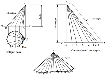
Method:
(i) Draw the plan of the base and divide it into equal number of parts e.g 12.
(ii) Locate point A1 and join each division on the plan to it.
(iii) Project these points upwards to the reference line X-Y to obtain the base of the elevation BC.
(vi) Join each point on BC to the vertex A to obtain the elevation.
True length
(v) Construct the true lengths to be used in the development by drawing a reference line X1Y1 and transfer
lengths A11, A12, A13 etc from the plan to it.
(vi) Join each point on line X1Y1 to the vertex A to obtain the true lengths.
Development
(vii) At any convenient position, draw a line equal to the true length A1 i.e line A1 on the development.
(viii)With A as centre on the development and radius A2 of the true length, swing an arc.
(ix) With 1 on the development as centre, radius equal to the distance 1-2 on the plan, cut the previous arc to obtain point 2 on the development.
(x) With A on the development as centre and radius A3 measured from the true length, swing an arc.
(xi) With 2 on the development as centre and radius equal to the distance 2- 3 on the plan, cut the previous arc to obtain point 3 on the development.
(xii) Repeat the same procedure to obtain points 4, 5, 6 and7 to finish one –half of the development. Complete the other half and connect the points with a French curve to complete the development.
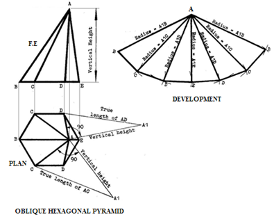
To draw the development of an oblique pyramid (hexagonal base)

Method:
(i) Draw the given elevation and plan.
(ii) From the elevation, sides AB and AE are represented in their true length but AC and AD are not.
(iii)To get the true lengths of AC and AD, draw a line equal to the vertical height at right angle to point A i.e AA1. Join A1 to C and D to obtain the true lengths A1C and A1D respectively.
Development
(vi) Draw a line equal in length to the true length of AE. With A in the development as centre and radius A1D (true length of AD), swing an arc each side of AE.
(vii)Then, with E on the development as centre and radius ED on the plan (length of one side), swing arc to cut each of the previous arcs at point D.
(viii) Similarly, with A in the development as centre and radius A1C (true length of AC), swing an arc to the side of AD.
(ix) Then, with D as centre and radius DC on the plan, swing an arc to cut the previous arc at C.
(x) Finally, with A as centre and radius A1B(true length of AB), swing an arc to the side of AC. With C ascentre, radius CB, swing an arc to cut the previous one at B.
(xi) Join the points to complete the development. If the base cover is required, then draw a regular hexagon on one of the base edges of the development.
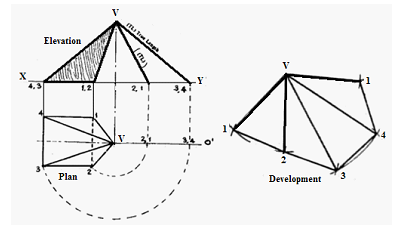 To draw the development of an oblique pyramid (square base)
Method:
(i) Draw the given plan and elevation.
(ii) Determine the true length of sides using rebatement method thus:
(iii)Extend the base line of the elevation and the centre line of the plan to the right.
(vi)With V on the plan as centre and radius V-2, swing an arc to cut the centre line of the plan at 2,1. Then project this line upward to cut the base line of the elevation. Join 2,1 to V. Line V-2,1 in the elevation is the true length of edges V-2 and V-1 of the pyramid respectively.
(v) Similarly, with V on the plan as centre and radius V-3, swing an arc to cut the centre line of the plan at 3,4. Project a line vertically upward from this point to the base of the elevation. Join 3,4 to V. Therefore, line V-3,4 is true length of edges V-3 and V-4 of the pyramid respectively.
To draw the development
(vi) Draw a true length e.g V-2.
(vii) With V as centre on the development, radius V-2,1 (true length) on the elevation, swing an arc. With 2 on the development as centre and radius 2-1 on the plan, swing another arc to intersect the previous one at point 1. Join 1-V and 1-2.
(viii) Similarly, with V on the development as centre and radius V-3,4 (true length) on the elevation, swing an arc. With 2 on the development as centre and radius 2-3 on the plan, swing another arc to intersect the previous one at point 3. Join 3-V and 3-2.
Complete the other half of the development.(note that lineV-1 and V-2 have the same true length. The same is V-3 and V-4) . If a base is required, draw the square on the plan on any of the base edges of the development.
WEEK SIX, SEVEN AND EIGHT
SURFACE DEVELOPMENT: INTERSECTIONS
CONTENT
(i) Meaning of intersection and intersection of cylinders.
(ii) Intersection of prisms, pyramids, cones and spheres.
Meaning of intersections
Intersections are formed when two surfaces meet. The surfaces can be plane, curved, or spherical. The intersection of two plane surfaces is a straight line. The intersection of a plane and a curved or spherical surface is a curved line. The intersection of curved or spherical surfaces is a curved line. The point at which a line intersects a plane or curved surface is called a piercing point.
Intersection of Cylindrical Pipes of Equal Diameter
Example: To draw the curve of intersection for two cylindrical pipes of the same diameter joined at right angle and the development of pipe B.

![]()
Method:
- Draw the given elevation and plan of the pipes.
- Draw a semi circle each on the elevation and plan of pipe B and divide each of them into six equal parts.
- Label each division as shown in the figure.
- Project horizontal lines from the points on the semi-circle of the plan to touch the plan of pipe A at points 01, 11, 21 and 31.
- Project vertical lines upwards from points 01, 11, 21 and 31 to meet their corresponding horizontal lines from the semi-circle of the elevation. This marks the line of intersection.
Note: The line of intersection for two cylinders of the same diameter is always a straight line.
To draw the development of pipe B, see figure C in the diagram.
Method:
(i) Draw a straight line at a convenient distance equal in length to the length of the semi-circle
i.e. transfer the distances on the semi-circle to the line DV and label as shown in the figure.
(ii) Project lines vertically upward from each division on line DV. Where these lines intersects with their corresponding lines from the curve of intersection labeled I0, I1, I2, I3 marks the development of pipe B.
Intersection of Pipes of Unequal Diameters
![]() To draw the curve of intersection of two cylindrical pipes of unequal (different) diameter joined at right angle.
To draw the curve of intersection of two cylindrical pipes of unequal (different) diameter joined at right angle.

Method: Same as that of equal cylindrical pipes. The only difference is that since the pipes are of different diameter, their curve of intersection is a curve instead of a straight line.
Intersection of Two Cylindrical Pipes of Unequal Diameters Which Intersect at an Angle
Example: Two pipes of unequal diameter intersect at an angle other than right angle. To draw the ![]() curve of intersection and the development of pipe B.
curve of intersection and the development of pipe B.

Method: Virtually the same as the previous ones.
(i) To draw the curve of intersection, lines are projected vertically upward from points 01, 11, 21 and 31 to intersect their corresponding lines projected from the points on the semi-circle of the elevation.
The points of intersection of these lines i.e. I0, I1, I2, I3 marks the curve of intersection.
(ii) Project lines at right angle from each point on the curve of the intersection to the sides of pipe B.
(iii)At a convenient distance from pipe B of the elevation, transfer the distances on the semicircle to the base lin MN as shown above. Note that the 12 divisions is the length of the circular shape of the pipe B.
(iv)Project lines from all the 12 divisions to intersect their corresponding lines from the points on the curve of intersection in order to obtain the development of pipe B. See figure Q on the diagram.
Evaluation Questions
1. Two cylinders intersect at 600 as shown below. Draw, full size, the (a) given elevation; (b) complete plan;(c) curve of intersection on the elevation; (d) surface development of pipe A.
![]()
2. Two unequal cylinders A and B intersect as shown in third angle below. Draw the: (a) curve of intersection ![]() of the cylinders; (b) surface development of cylinder B making XX the seam.
of the cylinders; (b) surface development of cylinder B making XX the seam.

3. The figure below shows the plan and incomplete elevation of two intersecting cylinders. Draw the plan and![]() complete elevation with the curves of interpenetration.
complete elevation with the curves of interpenetration.

Intersection of a Cylinder and a Cone
 Example: To draw the curve of intersection of a cylinder intersecting a cone as shownbelow.
Method:
(i) Draw the given elevation and plan of the intersecting cone and cylinder.
(ii) Draw a semicircle each on the cylinder of the elevation and plan. Divide these semicircles into 6 equal partsand label them as shown.
(iii) Project lines from each division on the semicircle of the elevation to meet the slant side of the cone i.e. QV at points A, B, C, D, E, F and G.
(iv) From points A, B, C, D, E, F, and G, project lines vertically downward to the centre line of the plan.
(v) With K at centre and radius A-1, 2-B, 3-C, 4-D, 3-E, 2-F, and 1-G, draw circles.
(vi) The intersection these circles with their corresponding lines projected from the plan of the cylinder make the points for the curves on the plan.
(v) From each point of the curve of intersection on the plan, project lines vertically upward to intersect theircorresponding lines from the semi-circle of cylinder X to obtain the curve of intersection on the front elevation.
Intersection of a Square Prism and a Square Pyramid
Example: To draw the line of intersection of a square prism and a pyramid respectively.
![]()
Method:
(i) Draw the given elevation and plan of the intersected prism and pyramid.
(ii) Draw the end view of the prism as represented by figure P.
(iii)Extend the centre line of the square prism to touch the edge of the pyramid at A. From this point A, project a line vertically downward to touch the edge of the plan at B.
(iv)From point B, draw a square parallel to the plan of the pyramid i.e.BLTS.
(v) Transfer the width 0-1 from the end elevation P and place them about the centre line of the plan of the prism.
(vi)The lines 1 on the plan of the prism intersects the square BLTS at point C. Project C vertically upward to meet the centre line of the square prism on the front elevation at point D.
(vii)Join DX and DY to get the line of intersection on the elevation. Then drop perpendicular lines from points Xand Y to meet the centre line of the plan at points Z and H respectively. Join CH and CZ to get the line of intersection on the plan.
Intersection of a Cone and a Sphere
![]() Example: To draw the curve of interpenetration of a sphere intersecting a cone.
Example: To draw the curve of interpenetration of a sphere intersecting a cone.
Method:
(i) Draw the given elevation and plan of the intersected sphere and cone.
(ii) Locate the centre of the sphere and draw a centre line A-1. Take any convenient unit and mark it each side of line A-1 in order to draw the horizontal lines B-2, C-3, D-4, B-6, C-7, D-8 then draw lines E-5 and F-9 which are not of equal unit with others.
(iii)Project lines downward to the centre line of the plan from points F, D, C, B, A, and E. With P as centreandradius FF1, EE1, DD1, CC1, BB1 and AA1, draw circular sections. Also, project lines downward to the centre line of the plan from points 9, 8, 7, 6, 1, 2, 3, 4 and 5. With Q as centre and radius 991, 881, 771, 661, 111,221, 331, 441 and 551, draw circular sections of the cone which intersect their corresponding circular section of the sphere to give the points for the curve on the plan.
(iv)Project the points on the curve of intersection on the plan vertically upward to meet their corresponding horizontal lines (sections) in order to obtain the curve of intersection on the front elevation.

Evaluation Questions
1. The figure below shows two views of a cone pierced by a cylinder. Draw the given views full size and curves of interpenetration.

![]()
![]() 2. The figure below shows two views in first angle projection of a cone pierced by a sphere. Draw full size the given views and the curves of interpenetration.
2. The figure below shows two views in first angle projection of a cone pierced by a sphere. Draw full size the given views and the curves of interpenetration.

READING ASSIGNMENT
Engineering drawing 2 by Parker and Pickup pages 38-76
WEEKEND ASSIGNMENT
1. Which of the options below represents the correct curve of intersection of two similar cylindrical pipes intersecting at right angle?

2. Which of the following shows the curve of interpenetration of two unequal cylinders?


![]() 3.
3. The intersection of a right cone and a cylinder are shown above. Which of the following shows the correct curve of interpenetration?
4. The point where two cylindrical pipes join or intersect is called A seam. B. Intercept. C. Piercing. D. Welding.


![]()
![]() 5. The figure above shows the elevation and plan of two intersecting cylinders. Which of the following optionsrepresents the correct surface development of cylinder P.
5. The figure above shows the elevation and plan of two intersecting cylinders. Which of the following optionsrepresents the correct surface development of cylinder P.

![]() THEORY
THEORY
1.
Two cylindrical pipes of equal diameter intersect as shown in the figure above. Using the data given, draw: (a) the given view; (b) the curve of interpenetration of the two pipes; (c) the surface development of the shorter pipe using a b as seam.
![]() 2. The figure below shows two views of a cone pierced by a cylinder. Draw the given views full size and curves of interpenetration.
2. The figure below shows two views of a cone pierced by a cylinder. Draw the given views full size and curves of interpenetration.

WEEK NINE
PICTORIAL VIEWS (DRAWINGS)
CONTENT
- Types of Drawings and Application
Types of Drawing
(a) Planning Drawings
(b) Survey Drawings
(c) Architectural Drawings (preliminary sketch designs, design or presentation drawings, working drawings, and measured drawings )
(d)Engineering drawings Pictorial – isometric or 3-dimensional drawing, oblique drawing, perspective drawing, and axonometric drawing.
Orthographic– 2- dimensional drawing)
Evaluation Questions
1. List four basic types of drawing.
2. Mention 3 types of architectural drawing.
Applications
1. Planning Drawings: These are drawings and diagrams made to show existing topography, roads, population, etc. It also shows some proposed new roads and zonal areas. statutory scheme maps and detailed new development layouts.
2.Survey Drawings: These type of drawings are used to show buildings, boundaries, water, arable lands, vegetation, roads, footpaths etc in a particular geographical location. Different colors are used to differentiate features e.g. Buildings – light crimson or neutral tint, Arable lands– sepia or burnt umber,
Water– Prussian blue which is darkest at the edge, Vegetation – dark green and Pastures – lightgreen. The true North must be clearly indicated on this type of drawing.
3.Architectural Drawings: Architectural drawings are classified into different types and these include-preliminary sketch designs, design or presentation drawings, working drawings and measureddrawings.
Preliminary Sketch Design-: This is a freehand sketch made during the process of trying to work out the main design. The sketch may include roughly set-up plan and elevation. The purpose of a sketch design is to arrive at a solution of major problems and should therefore be tentative in nature.
Design or Presentation Drawing-: This is a finished design drawing ready for presentation to a Client. Therefore, it should show a minimum of constructional details. Although, the construction must be fully worked out before they can be properly completed. The drawings may be in orthographic,isometric, or perspective projection respectively, accurately drawn and effectively rendered.
Working Drawings-: These are detailed, fully worked out drawings from which the actual construction work is carried out. They must therefore give all the graphical information necessary for constructional purposes and must be accurately drawn in orthographic projection of plan, elevation and essential sections.
Measured Drawings-: These are scale drawings made from carefully taken measurements of existing buildings of historic interest and architectural merit. This could be used as part of students training in design or for the purpose of record keeping. It may illustrate a whole building or part of a building.
4.Engineering Drawing: This could either be Pictorial (3 – dimensional) e.g. isometric, oblique, perspective and axonometric, or Orthographic (2- dimensional) projected in plans, elevations and arranged either in First angle or Third angle.
General evaluation Questions
1. List and explain four types of drawing?
2. State the uses of the following types of drawing. (a) working drawing (b)survey drawing?
3. Sketch the Front, rear (back), end views and pictorial drawing of your house.
4. Imagine a local community and make a survey drawing of it, Showing the buildings,foot paths, green vegetation and other captivating features.
READING ASSIGNMENT
E- learning notes and visit goggle for types of drawing and applications
WEEKEND ASSIGNMENT
- Drawing is generally classified into the following types except A. planning B. survey C. engineering D. measured.
- Architectural drawings are classified into the following types except A. working.
B. survey C. preliminary sketch design. D. design or presentation
- The following are examples of engineering drawing except A. Isometric B.orthographic C. obliqueD. planning
- Which of the following types of engineering drawing is represented in plan, elevation and section? A. Isometric. B. Oblique. C. Perspective. D. Orthographic.
- In survey drawing, which of the following colors is used to represent water? A. Dark blue.B. LightPrussian blue C. Light green D. Dark green.
THEORY
- List and explain four types of Architectural drawing.
- State three basic types of drawing and their applications.
WEEK TEN AND ELEVEN
TOPIC: PICTORIAL DRAWINGS (ISOMETRIC, OBLIQUE AND PERSPECTIVE)
CONTENT
- Meaning of pictorial drawing.
- Types of pictorial drawing.
Meaning of Pictorial Drawing
A pictorial drawing as the name implies is that which is represented in its true picture. It is also referred to as three dimensional drawing since it shows the length, height and depth of the object. Pictorial drawing falls into three main types namely: Isometric, oblique and perspective.
Evaluations
1. What is pictorial drawing?
2. Give three types of pictorial drawing.
Types of Pictorial Drawing
Isometric Drawing-: This is the type of pictorial drawing in which the receding lines are drawn at 300 to the horizontal and other lines are drawn vertically. All lines are drawn in their true lengths. The axes on which isometric drawing is made is called ‘isometric axes’. Each axis is spaced at an angle of 1200from each other as shown below. An axis may be placed at any position provided it is 1200 apart from the next one.


Fig. Isometric axes Fig. A cubeFig. A solid block
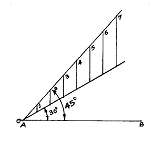
Isometric Scale-: This is the scale used in finding the true isometric projection of an object from the normal conventional isometric {equal angular measurement} projection. See the figures belowfor more illustration.

![]()
Method:
(i) Draw line AC. This is one of the diagonals of the face ABCD of the cube shown in figure 6.
(ii) Construct line AB such that AB is inclined at an angle of 450 to AC
(iii) Construct line AE such that AE is inclined at an angle of 300to AC. Therefore, AB represents the measurement of the object while AE is the true isometric measurement of the object.
Note: Any measurement made or taken along line AB is the object measurement such as A1, A2 and A3. The perpendicular lines drawn from these points to line AE will mark points 11, 21 and 31. Thus the measurement A11, A21 and A31 are the true isometric measurements.
Circles, Arcs and Curves in Isometric
Circles in Isometric:Circle in isometric form appears like an ellipse. There are different methods of drawing a circle in isometric projection and these include: Four-centered approximate ellipse, ordinate or grid and offset methods.
Four-centered approximate ellipse method
For instance, to draw a circle of diameter 2cm in isometric using the four-centered method, follow the procedures below:

![]()
Fig. Four-centre method
Method:
(i) Draw a square in isometric equal in size to the diameter of the given circle. Bisect each side.
(ii) From point A, draw lines to meet the mid-points of line BD and BC at H and G respectively.
(iii) Repeat the procedure in (iii) with point B to get points E and F respectively.
(iv) The point of intersection of these lines i.e. I and J are centers of arc.
(v) With I as center and radius IE or IF, draw an arc EH. Repeat same with center J to draw arc FG.
(vi) With A and B as centers draw arcs GH and EF respectively to complete the circle.
Ordinate or Grid Method
![]()
![]() For instance, to draw a circle of diameter 2cm in isometric using the ordinate or grid method, follow the procedures below:
For instance, to draw a circle of diameter 2cm in isometric using the ordinate or grid method, follow the procedures below:


Normal Circle Isometric Circle
Method:
(i) Construct a square A1B1C1D1 of same diameter to enclose the given circle in orthographic.
(ii) Draw a line E1F1 as the horizontal diameter of the circle.
(iii) Divide the square into any number of equal parts called ordinate or grid i.e. a, b, c, d, e, f andg. as the case may be. Take note of the distances of the points where each grid cuts the circle.
(iv) Construct a square A1B1C1D1 of same diameter in isometric and repeat exactly the same division asin the plane square on it.
(v) Transfer distances along each grid of the normal square to its corresponding grid of the isometric square. The positions of these distances mark out the circle in isometric. See figures above.
Offset method
![]()
![]() For instance, to draw a circle of diameter 2cm in isometric using the offset method, follow the procedures below:
For instance, to draw a circle of diameter 2cm in isometric using the offset method, follow the procedures below:


Normal Circle Isometric Circle
Method:
(i) Construct a square WXYZ of equal size as the given circle to enclose it.
(ii) Determine the mid points L, Q, M and P of the square.
(iii) Draw diagonals WY and XZ.
(iv) Determine the points c, r, d and s where the diagonals cut the circle.
(v) Draw a square in isometric of same size as the square in (i)
(vi) Repeat steps (ii) and (iii).
(vii) Transfer the lengths Z-a and Z-b of the plane square to the isometric square to get point c.
Use same method for points r, d, and s respectively.
(viii) Join points c, P, r, M, d, Q, s and L to get the circle in isometric form.
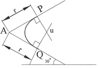
Drawing of Arcs in Isometric:The method of drawing arcs in isometric is the same as the four– centered method of drawing circles. Here, it is not necessary to draw the entire isometric square since an arc is only a part of circle.
Method:
(i) From the corner A where the arc is to be drawn, lay off the radius r of the arc equally on both edges.
(ii) From each of these points P and Q respectively, draw perpendicular lines
(iii) The point of intersection u of these perpendicular lines marks the center of the arc to be drawn. With u as center and radiusuPor uQ draw the required arc PQ.
Drawing of Irregular Curves in Isometric:The ordinate or grid method of drawing circles in isometric is appropriate for this purpose. This is done by drawing lines or ordinates at equal spacing on the orthographic view of the object to the same scale as the isometric. Distances are then transferred with a divider on the isometric axis of the object to be drawn. See the figures below for more illustration.
Method:
(i) Draw a series of equally spaced parallel lines (ordinates) on the given plane view.
(ii) Where each ordinate line intersects the curve forms a coordinate point.
(iii) Draw an isometric axes of the same dimensions as the given plane view.
(iv) Repeat step (i) on the drawn isometric axes.
(v) With a pair of dividers, transfer the coordinates of the plane view to the isometric view. The rear face ie the thickness is drawn the same way.
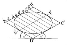
Oblique drawing
Oblique Drawing:Oblique drawing uses three axes just like isometric drawing. In oblique drawing, two of the oblique axes are placed at right angle to each other. The third axis (receding) is placed at any convenient angle (300, 450 or 600) to the horizontal. See the figures below for oblique axes. All receding edges are drawn parallel to this third axis.

 There are three classifications of oblique drawing. These include cavalier, cabinet and general oblique respectively.
Fig. Oblique axes
![]() Cavalier Oblique-This is the type of oblique in which the receding axis (depth) makes any angle usually 300 or 450 with the horizontal and is drawn full length there by having equal length with the depth and height. See diagram below. The depth of the cube appears to be longer than the length and height. Actually, they are equal. This distortion could be eliminated by reducing the angle of the receding axis.
Cavalier Oblique-This is the type of oblique in which the receding axis (depth) makes any angle usually 300 or 450 with the horizontal and is drawn full length there by having equal length with the depth and height. See diagram below. The depth of the cube appears to be longer than the length and height. Actually, they are equal. This distortion could be eliminated by reducing the angle of the receding axis.

Cabinet Oblique-Cabinet oblique used the same principles of construction with cavalier oblique except that the receding axis which could be drawn at any angle of either300, 450 or 600 to the horizontal is actually drawn half full length.

![]() General Oblique-This is one in which the receding axis (depth) could be drawn to lengths ranging from half to full length. The scale is reduced until the object appears most natural. The angle between the receding axis and the horizontal is usually drawn between 300 and 600.
General Oblique-This is one in which the receding axis (depth) could be drawn to lengths ranging from half to full length. The scale is reduced until the object appears most natural. The angle between the receding axis and the horizontal is usually drawn between 300 and 600.

Circles, arcs and curves in oblique
Drawing of Circles and Arcs in Oblique:Circles and arcs in obliquearedrawn almost thesame way as in isometric drawing. Cavalier oblique can be drawn by using the four-centered method while Cabinet and General oblique on the other hand can be drawn using the offset method.
Four-centered approximate ellipse method
For instance, to draw a circle of diameter 2cm in cavalier oblique using the four-centered method, follow the procedures below:

Method:
(i) Draw a square on the receding axis equal in size to the diameter of the circle to be drawn.
(ii) Bisect all the sides of the square to get the mid point of each side.
(iii) From each midpoint, erect a perpendicular line towards the inside of the square.
(iv) The points of intersection of these perpendicular lines mark the four centers of the arcs that draw the circle.
Note: If the angle which the receding axis makes with the horizontal is less than 300, these perpendiculars will intersect inside the oblique square. Otherwise, they will intersect outside the oblique square.
 Offset Method: Same as isometric. See diagram above for more illustration.

Normal circle Oblique circle
Evaluation Questions
1. Draw full size in isometric projection the pivot block shown below.

 2. Draw full size in isometric projection the object shown below.
READING ASSIGNMENT
Drafting technology and practice by William P. Spence. Pages 394 – 408
Engineering drawing 1 by M.A.Parker and F.Pickup pages 43 – 64
WEEKEND ASSIGNMENT
1. The type of pictorial drawing in which one of the receding axis is drawn at right angle is called A. isometric. B. oblique. C. perspective D. axonometric.
2. Vanishing point is the characteristics of which of the following types of pictorial drawing?
A. Isometric B. Perspective C. Oblique D. Axonometric.
 3. The appropriate name given to the scale shown below is A. diagonal. B. isometric
C. oblique D. plain.
4. Circles in isometric projection has the shape of A. rectangle B. parabola C. ellipse.
D. hyperbola.
5. Isometric axes are spaced at what angle to each other? A. 300. B. 600. C. 900. D. 1200.
THEORY
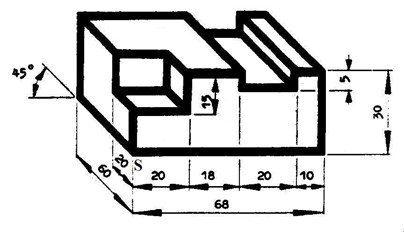
1. Draw the engineering block shown below in oblique projection using S as the lowest point.
2. Draw the bolster block shown below in isometric projection using X as the lowest point.