Share this:
FIRST TERM E-LEARNING NOTE
SUBJECT: TECHNICAL DRAWING CLASS: SS3
SCHEME OF WORK
WEEK TOPIC
1-2 Revision
- Engineering Designs and Working Drawings
- Screw Thread
- Fasteners
- Locking Devices.
- Sectioning- Types
- Sectioning continued.
- Sectioning continued.
- Block sectioning- Solid Blocks and Assembled parts.
WEEK THREE
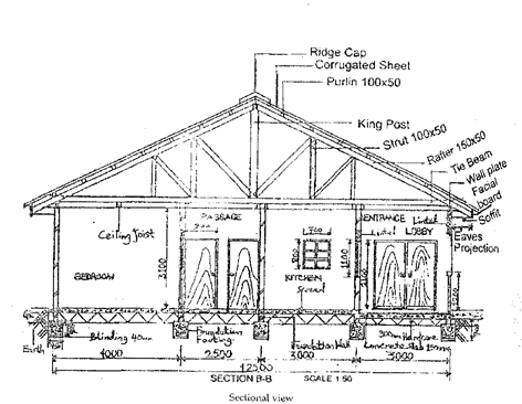
WORKING DRAWING OF A BUNGALOW BUILDING
CONTENT
MEANING AND EXAMPLES OF WORKING DRAWINGS
WORKING DRAWINGS
They are the drawings from which the actual construction work is carried out. They must therefore give all the graphical information necessary for constructional purposes and must be accurately drawn in orthographic projection of plan, elevation and essential sections.


EVALUATION
- What are working drawings?
- State five features of a working drawing.
- Draw a working drawing of a funnel.
GENERAL EVALUATION
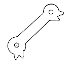
- Drawing the working drawing of a flat spanner.
- Draw a working drawing of your dream bungalow building.
READING ASSIGNMENT
Visit the internet and read more about working drawings on mechanical and building.
WEEKEND ASSIGNMENT
- Working drawings are represented in A. isometric B. oblique C. axonometric
D. orthographic
- Which of the following features is not present in a working drawing? A. Sections B. Part description C. Drawing scale D. Jamb.
- The following are used while presenting a working drawing. A. sections. B. plan. C. front D. perspective.
- Which of the following is not in the group? A. Living room. B. Sitting room. C. Window. D. Column.
- Which of the following is not necessary in a working drawing? A. Dimensions B. Sections C. Scale D. Axonometric.
THEORY
- Draw freehand the working drawing of your dream bungalow building.
- Draw the working drawing of a funnel.
WEEK FOUR
DRAWING OF SCREW THREADS AND SPRINGS (APPLICATIONS OF HELICES)
CONTENT
- Screw Threads – Meaning, Terminologies, Conventional Representations and Types
- Screw Threads – Parts /Features.
- Springs and other Conventional Symbols.
The principles of helix is applicable in the construction of the following: Screw threads, springs, Worm gears, propeller blades and cylindrical cams
MEANING OF SCREW THREAD
A screw thread is a helical groove which is cut, rolled or sometimes cast on a cylinder or in a cylindrical hole. The thread form could be compared to a string wound uniformly round a cylinder. Thread made outside a cylinder is called external thread while that made inside a cylindrical hole is called internal thread. Generally, screw threads are the holding power for bolts, screws, studs and nuts. They are used for fastening and transmission of power.
TYPES OF SCREW THREADS
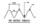
- ISO METRIC THREAD
This type of thread has the form of vee which makes it suitable to fasten parts together and to adjust the positions of parts. The flanks of an isometric thread are inclined at an angle of 600. Because of this inclination to the axis, bursting forces are set up in the nut thus making it suitable for its purposes. ISO metric thread is designated as follows: M17 x 1.6 – 8H is for internal thread. M9 x 0.65 – 8g is for external thread. M ( thread symbol for isometric.), 17 and 9 ( nominal diameters inmillimeters ), 1.6 and 0.65 ( pitch in millimeters ), 8H and 8g (thread tolerance class symbols).
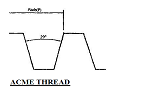
- ACME THREAD
This type of thread is used to fasten parts together, adjust the position of parts and totransmit power. The thread angle is 290.
- BUTTRESS THREAD
This type of thread is used to transmit power in one direction only. The thread angle is 450.
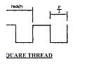
- SQUARE THREAD
The flanks of a square thread are normal to the axis, bursting forces are not present andthus making it theoretically ideal for power transmission. It is used on the operating spindles of valves, jacks and on lathe machine to move the cross slide.
- BRITISH ASSOCIATION THREAD
The British Association thread uses metric sizes and it is used extensivelyfor instrument work such as electrical and aircraft works. The sizes are designated by numbers rangingfrom 0 to 25. The 0 British Association thread has a diameter of only 6mm while the 25 British Associations thread has a diameter of 0.25mm.
Other types of British threads are
- British Standard Fine(BSF)
- British Standard Whitworth (BSW)
- British Standard Pipe ( BSP) which is used for piping andtubing.
Note: British Association thread has its flanks inclined at angle 47.50 while that of British Standard Whitworth is inclined at 550


EVALUATION
- Explain the following thread terms: Pitch, Lead, Single – start thread, Multi – start thread, Crest, Root and Thread angle.
- List 5 types of thread.
- With the aid of suitable diagrams, explain 4 types of thread.
SCREW THREADS – PARTS /FEATURES

Pitch: The pitch of a thread is the distance from a point on one thread to an identical point occurring nextto it. It is measured parallel to the axis in an axial plane.
Lead: The lead of a thread is the axial movement of a screw in one revolution.
Single – start thread: In this type of thread, the pitch and the lead are the same.
Multi – start thread: This consist of two or more ridges, there by producing a lead that is greater than the pitch. Therefore, a two – start thread has twice the length of a single – start thread ie twice pitch = 1 lead. The same is applicable to a three– start thread; lead = thrice pitch and so on. Multi – start threads are used where fast movement is desired with a minimum number of rotation rather than holding.
Crest: This is the meeting point of the two flank lines forming the thread. It may either be round or flat.
Root: This is the bottom groove formed by two adjacent flanks forming the thread.
The flanks of a thread are two straight lines either joining to form the crest or the root.
Thread depth: This is half the difference between the major and minor diameters.
Major diameter: This is the full outside diameter. The length is measured at right angle to the axis from crest to crest (external thread) or from root to root (internal thread).
Minor diameter: This is the diameter at the root of an external thread or the crest of an internal thread when it is measured at right angle to the axis. It is called the root or core diameter.
Thread angle: This is the angle formed by the two adjacent flank lines.
Effective diameter: This is the same as the pitch diameter.
Right – hand thread: A thread is form is right –hand if the thread slopes towards the right.
Left – hand thread: In this case, the thread slopes towards the left.
CONVENTIONAL REPRESENTATION OF SCREW THREAD


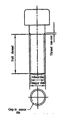
When an external thread is viewed longitudinally, e.g. bolt, the major diameter is shown by a pair of thick lines and the minor diameter by a pair of thin lines. The end of the full thread ie where the root ceased to be fully formed, is drawn as thick line.
INTERNAL THREAD IN SECTION
For internal thread in section, the minor diameter is drawn in thick lines while the major diameter is drawn in thin lines. Note that the hatch line crosses the major thread and stops at the minor diameter.
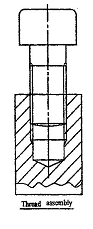
A SECTION THROUGH A THREADED ASSEMBLY
On this arrangement, the screw is shown as an outside view and so, its thread covers the thread in the tapping as shown in the figure below.
EVALUATION
- Differentiate between a pitch and a lead
- Draw the sectional view of a bolt.
- Differentiate between single and multi-start thread.
- Draw the symbol of a bolt and nut.
SPRINGS
HELICAL SPRING
This is a spring whose construction is based on the principles of helix. There are two types of helical spring and these include
(i) Compression spring
(ii) Tension spring
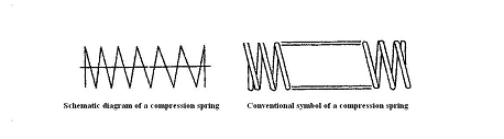
(i) Compression spring:
This can be found in the suspension unit of motor vehicles and other machines.
 They can be identified by the flatness of the ends which makes it possible to conveniently fit into theparts. They are used as shock absorbers in vehicles.
 (ii) Tension spring: This type of spring can be identified by the round hook at both ends of the spring whichmakes it possible to be attached to objects. It is used in wrist watches and automobiles units.
THE CONSTRUCTION OF A HELICAL SPRING

METHOD
The method of construction is same as that of a helix. Except that a circle equal in diameter to the thickness of the spring is drawn at each point. Curves are then drawn tangential to the circles to form the spring.
LEAF SPRING
This type of spring may have the form of a single cantilever type or may be laminated i.e semi-elliptical in design. The laminated form is used for shock absorbers in motor vehicles.


GENERAL EVALUATION
- Draw two complete turns of a right- hand helical spring, 76mm mean diameter, 48mm pitch,made from 16mm diameter wire.
- Draw two complete turns of a left-hand helical spring, 120mm outside diameter and 36mm pitch, made from 15mm square section wire.
- Using suitable diagrams differentiate between tension spring and compression spring.
- Differentiate between right and left hand thread.
READING ASSIGNMENT
Engineering Drawing 1 by M.A Parker and F.Pickup Pages 32 – 40.
Instructional Materials: Screw threads and springs.
WEEKEND ASSIGNMENT
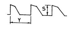
 Use the figure below to answer 1 and 2.
- What type of thread form is shown above? A. ACME. B. Whitworth. C. Buttress. D. Square
- S in the figure represents. A. Lead. B. Pitch. C. Root. D. Depth.
- If a thread is designated as M8 x 1.6, what does 1.6 represents?
A. Pitch B. Lead C. Minordiameter. D. Major diameter.
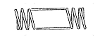
 The conventional symbol shown below represents?
A. Leaf spring. B. Compression spring.
C. Tension spring. D. Bending spring
 The conventional symbol shown below represents?
A. Compression spring. B. Tension spring.
C. Semi- circular spring. D. Semi- elliptical spring.
THEORY
- Draw two complete turns of a right- hand helical spring, 76mm mean diameter, 48mm pitch,made from 16mm diameter wire.
- With the aid of suitable diagrams, explain 4 types of thread.
WEEK FIVE
FASTENERS
CONTENT
(i) Meaning andTypes of Fasteners.
(ii) Conventional Representation and Construction.
MEANING AND TYPES OF FASTENERS
A fastener as the name implies from the word fasten is simply an object or equipment used to “hold tight” or tie two or more components together.
Fasteners are of two forms and these include temporary fasteners and permanent fasteners. While the temporary fasteners are used where maintenance or periodic checking is necessary, permanent fasteners on the other hand are used where periodic maintenance operations are not necessary. Examples of permanent fastening methods are Riveting, Welding, Soldering and Brazing. Moreover, the commonest temporary fasteners are Nuts, Bolts, Screws, Studs and Washers.
PERMANENT FASTENERS
WELDING
This is one way that metals could be fastened together permanently. This has been treated in week one. Welding is a permanent fastener in the sense that once mating parts is joined either by fusion or resistance method, it will take some special cutting tools to separate them.
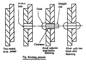
RIVETING
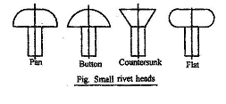
This is the method of using rivets to fasten metals or plastic parts together permanently. This does not require heat unlike welding. During riveting, the parts to be joined are drilled in the right position and a rivet whose head end is attached to a riveting machine is passed through the drilled hole with its straight end. When the machine is operated, the straight end increases in size and tightly fit into the drilled whole and also form another head at the other end of the fastened parts. See diagrams below.
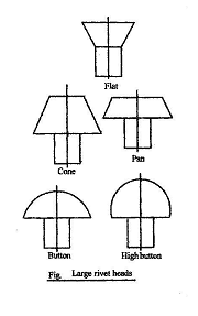
The major feature used in differentiating rivets is basically the head formation. Small rivets are made with pan, button and countersunk heads having shank diameters of between 1.5mm to 11mm. Large rivets are made with button, high button, pan, flat top, countersunk and cone head respectively. They have shank diameters in the range of 12mm and 43mm. Below are diagrams showing different types of rivet heads.


SOLDERING
This is the process of joining or fastening metals together by means of heat and a suitable alloy. There are two types of soldering and these are soft and hard soldering. Soft soldering is a low temperature form in which an alloy of Tin and Lead with the addition of Antimony and Bismuth are used to join parts together. Hard soldering is a high temperature form of soldering which includes brazing and silver soldering. Silver soldering makes use of a solder which is an alloy of Copper, Zinc and Silver.
BRAZING
This is the process of joining metals by the use of a solder often called Spelterwhich is an alloy of Copper and Zink in strip, wire or granulated form. A temperature of approximately 9000C is needed for brazing.
TEMPORARY FASTENERS
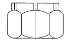
NUTS
A Nut is a thick square or hexagonal or octagonal piece of metal having a threaded hole into which a bolt fits. The threads are cut inside the nut using an instrument called Tap. For extremely large nuts, a machine called Lathe is used. The hexagonal shape is preferred for nuts and the heads of screws and bolts because it takes less space and is lighter than both square and octagonal shapes. Moreover, if a spanner of the same size could bring a hexagonal shape to a position that is one-sixth of a turn, the same spanner going through same distance would turn a square shape only through one-fourth. Although the octagonal shape would be one-eighth of a turn which should have been more preferred to others but the only disadvantage is that a spanner could easily slip round the corners since its flats are smaller.
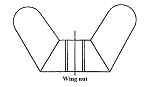
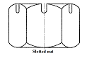
There are different types of nut and these include Castle, Slotted, Lock, Wiles’ and Wing nut respectively. See the figures below for types of nut.
CONSTRUCTION OF A HEXAGONAL NUT


Third view
METHOD
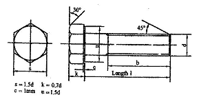
Given the major diameter of the thread d, draw the chamfer circle with a diameter of 1.5d equal to the distance across flats (A/F). Use 600 setsquares to construct a hexagon round the chamfer circle. For distance across corners (A/C), use 2d to draw the chamfer circle.
Draw the two thread circles representing the major diameter, d and the minor diameter. The minor diameter need not be precise but a diameter of 0.75d or 0.8d is sufficiently accurate.
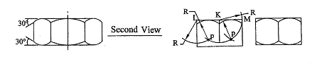
Project lines downward from the corners of the first view to start the second view. Make the thickness of the nut to be 0.8d. For bolt head use 0.7d. With T as center and radius R where R is equal to half the distance across flats, draw an arc to cut the center line at point Q. With Q as center and same radius, draw another arc below the first to cut the center line at point P and the first arc at points V and W. These are the centers of the chamfer curves. Repeatsame for the other side to complete the second view. For the thickness of thin nuts, R is 0.6d.
Project lines from the top and bottom of the second view to start the third view. Make the width of this view equal to the distance across flats, 1.5d. With K as center and radius R, draw an arc. With L and M as center in turn, and radius R, draw arcs to cut the first at points A and B. These are the centers of the two chamfer curves. Repeat same for the other side to complete the third view.
NOTE
The 300 chamfer does not show on the End view but have squared corners as seen on the end view. On the Front elevation, it forms parabolas on the flats while on the Plan, it appears like a circle touching the flats. Hence the name chamfer circle.
BOLTS
The standard bolt is made up of a hexagonal head with a chamfer angle of 300 and a cylindrical shank (normally parallel). The free end of the shank is threaded from the tail end a distance equal to twice the diameter of the bolt plus some units or tens of a millimeter depending on the length of the shank. It is on this threaded length that a nut is screwed. The tip of the threaded length is chamfered at an angle of 450. The rest of the shank up to the underside of the bolt head is left unthreaded. The nominal length l, of a bolt or screw does not include the thickness of the head. The instrument used in cutting threads on a bolt is called Die. For extremely larger sizes, a Lathe machine is used. See the diagram below for more illustration.

THREADED LENGTHS OF A BOLT
For nominal length l, up to 125mm, the threaded length b, should be 2d + 6mm where d is the major diameter of the bolt. If l is from 125mm to 200mm, b should be 2d + 12mm and if above 200mm, b should be 2d + 25mm.
Construction of a bolt

METHOD
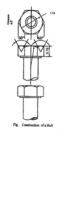
Draw the top view of the bolt head by drawing a chamfer circle equal to the distance across flats or 1.5d where d is the major diameter of the thread.
Use 600 setsquares to construct a hexagon round the chamfer circle.
Project lines downward from the edges of the first stage to start the second stage.
Mark off 0.7d as the thickness of the bolt head.
Locate the centers of the smaller curves by drawing lines at angle 600 as shown in the diagram. The center of the large curve is obtained by trial and error method. But the arc should meet the smaller arcs and also make tangent with the top of the bolt.
Draw the top corners at a chamfer angle of 300.
Remove the construction lines and darken the drawing.

Bolt and nut assembly
EVALUATION
- Differentiate between a fastener and locking device.
- With the aid of suitable diagrams, state 5 types of rivet head.
- Differentiate between soldering and brazing.
- Draw the diagrams of the following types of nut.
- Slotted nut.
- Castle nut.
- Lock nut.
- Wiles’ nut.
- Wing nut.
- Draw twice full size in first angle projection, three views of an M20 hexagonal nut.
- Using third angle projection, draw three views of an M24 hexagonal bolt with a washer faced head and a nominal length of 120mm. Calculate the thread length. Show the threaded end chamfered.
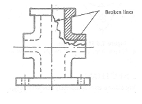
CONVENTIONAL REPRESENTATION OF BOLTS AND NUTS
Bolts are threaded outside unlike nuts that are threaded inside. The break in either the major(outside) diameter circle or minor(inside) diameter circle signifies “not threaded”. Therefore, for bolts that are threaded outside and not inside, the broken circle appears inside. The reverse is the case for nuts that have their thread inside and not outside. See diagrams below.


A Bolt A Nut
GENERAL EVALUATION
- Draw diagrams showing the conventional representation of (a) Nut. (b) Bolt
- Draw suitable diagrams to show a bolt and nut assembly.
- Differentiate between permanent and temporary fasteners. Give 4 examples each.
READING ASSIGNMENT
Engineering drawing 1 by M.A.Parker and F.Pickup Pages 110 – 120.
Technical drawing for school certificate and GCE by J.N Green Pages 245-249.
Drafting technology by Spence Pages 319-321.
Instructional Materials: Bolts, nuts, washers, metal furniture and other relevant class room fittings
WEEKEND ASSIGNMENT
- In the construction of a bolt or screw, the nominal length includes the thickness of its head.TRUE or FALSE?
A. False. B. True. C. Neither true nor false. D. Partly true and false.
- The threaded bolt head and end are respectively chamfered at what angle?
A. 450 and 300B. 300 and 450 C. 600 and 300 D. 450 and 1200.

- The conventional symbol shown above is used to represent
A. Rivet B. Bolt C. Nut D. Weld
- In order to determine the threaded length of a bolt, an engineer specified 2d + 12mm. What does the letter d implies?
A. Nominal diameter B. Minor diameter C. Major diameter D. depth of thread.
- What is the name given to the fastener shown below?
 A. castle nut. B. wing nut. C. spring washer. D. slotted nut
THEORY
1. State 4 types of nut.
2. Draw twice full size in first angle projection, three views of an M20 hexagonal nut.
WEEK SIX
LOCKING DEVICES
CONTENT
(i) Meaning and types of locking device.
(ii) Examples of locking device.
MEANING AND TYPES OF LOCKING DEVICE
A bolt and nut assembly on a machine is likely to slacken off gradually due to vibration. To forestall this kind of condition, locking devices are used. They help to keep the fasteners in place. The two common types of locking devices are the frictional and positive locking devices.
A locking device is frictional if it acts to increase the frictional force between the fasteners e.g. bolt and nut and thus prevents slackening due to vibration.
A positive locking device on the other hand does not increase friction but simply keep the fasteners in place.
EVALUATION
- What is ‘frictional locking device’?
- What is ‘positive locking device’?
EXAMPLES OF LOCKING DEVICE
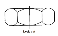
Locknut: This is a frictional locking device. It thrusts the thread of the standard nut against the thread of the bolt thus increasing friction and preventing slackening.
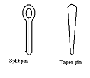
Split pin: this is a positive locking device. This is driven through a hole drilled in a bolt. When the nut is screwed down, the pin is driven in place with its legs bent over a flat surface on the nut. Note that the top face of the nut should bear against the pin and the pin should tightly fit into the hole.
Lock washers: These are frictional locking devices. An example of these types of washers is spring washer. When a nut is screwed down on it , it thrusts the thread of the nut against that of the bolt and thus produce a frictional lock.
Taper pin: This is a very good positive locking device especially if its end is split and the legs opened round the flats of the nut. This is driven through a common hole drilled in the bolt and nut. The only disadvantage is that it is difficult to align hole if the nut is removed.
Slotted nut: This is a positive locking device. A split pin passes through one slot and a hole in the bolt and the legs of the pin are opened and bent round the faces of the nut.
Castle nut: This is a developed form of slotted nut. It is a positive locking device.
Stiff nut: This is a frictional locking device. One type of stiff nut has a collar whose internal diameter is less than the thread minor diameter inserted into it. When the nut is screwed on the bolt, the thread of the bolt forces itself through the collar which is made of fibre or nylon and thus providing.
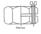
Wiles’ nut: This is a frictional locking device. Since this type of nut is sawn half way and a set screw is screwed on it , this result into a spring effect which makes the threads of the bolt and nut to jam and thus providing a frictional lock.
Ring nut: This is used on marine engines. They are positive locking device.
Locking plates: These are positive locking devices.
Tab washers: These are positive locking devices. They are commonly of three forms. Two of these have only one tab washer while the third form has two tab washers. This type is called Siamese.
Wire locking: This is a positive locking device.
Serrated locking plate: This type of locking plate provides a positive lock.
Collars: These are cylindrical objects made of either fibre or nylon. They are usually inserted into a nut to provide a frictional lock. When the nut is screwed on to the bolt, the bolt threads force their way through the collar which grips them tightly thus providing a frictional lock.
Washers: There are three main types of washers namely: Plane, Spring, and Star washers.
Plain Washers: They are used under the head of a bolt or nut. Their function is to spread the load over a large area than either the bolt head or nut.
Spring Washers: They are split and bent in a helical shape. They provide a frictional lock in bolts and nuts because of its spring action which makes the bolt thread to lock up with that of the nut. They also make it easier to unscrew bolted parts.
Star Washer: They are just like stars hence the name star washer. They are very useful for both internal and external projections. See diagrams below for other types of locking devices.


Siamese tab washer


EVALUATION
- Categorize the following locking devices into frictional and positive: Castle nut, Slotted nut, Taper pin, Split pin, Spring washers, Plain washers, Ring nut, Tab washers, Wiles’ nut, Stiff nut and lock nut.
- Draw the diagram of the following locking devices: Spring washer, siamese tab washer, Split pin, Taperpin, Castle nut, Wing nut, Slotted nut and Grub screw.
READING ASSIGNMENT
Engineering drawing 1 by M.A.Parker and F.Pickup pages 122 – 129
Technical drawing for school certificate and GCE by J.N Green pages 248-249.
WEEKEND ASSIGNMENT
- Which of the following is not a locking device?
A. bolt. B. lock nut. C. spring washer. D. split pin.
- Which of the following is not a positive locking device?
A. spring washer. B. ring nut. C. tab washer.D. taper pin.
- What is the name given to the locking device shown below?
 A. Siamese tab washer. B. Castle nut. C. Luck nut. D. wing nut
 - Which of the following is not a frictional locking device?
A. spring washer. B. stiff nut. C. wiles’ nut D. castle nut.
-
 The name given to the locking device shown below is
A. wing nut. B. Siamese tab washer.
C. spanner. D. locking plate
THEORY
1. Categorize the following locking devices into frictional and positive: Castle nut, Slotted nut, Taper pin, Split pin, Spring washers, Plain washers, Ring nut, Tab washers, Wiles’ nut, Stiff nut and lock nut.
2. Draw the diagram of the following locking devices: Spring washer, siamese tab washer, Split pin, Taper pin, Castle nut, Wing nut, Slotted nut and Grub screw.
WEEK SEVEN
SECTIONING: FULL, HALF AND PART SECTIONS
CONTENT
(i) Meaning of Sectioning.
(ii) Full, Half and Part Sections.
MEANING OF SECTIONING
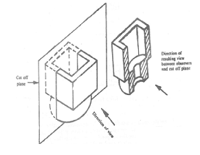
Sometimes, the interior parts of an assembled component need to be viewed, therefore, a cutting plane is assumed to have cut through the part and then the cut surface (section) can be viewed. This process is called sectioning.
EVALUATION
1. What is sectioning?
2. Illustrate with a diagram the line type used in sectioning an object.
FULL, HALF AND PART SECTIONS
FULL SECTION
 A full section is one in which the cutting plane extends fully through the entire object, cutting it into two equal halves. The position of the cutting plane is selected by the draughtsman to show the interior of the object to the best advantage. The cutting plane line is often omitted on full sections because its location is obvious.
Full section
HALF SECTION
If an object is symmetrical, its interior details can be fully described by cutting half way through the object. The resulting view is called half section.

Half section
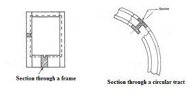
PART OR SCRAP SECTION
This type of section is similar to a “broken-out” section because a free hand break line is used. The only difference is that the sectional view is drawn away from the original object and labeled as section A-A or B-B as the case may be just like “removed section.”

Part or Scrap section
EVALUATION
1. Draw the diagram to illustrate a part section.
2. With the aid of suitable diagrams, illustrate: (i) Full section. (ii) Half section.
READING ASSIGNMENT
Engineering drawing 1 by Parker and Pickup.Pages 78 – 93.
 WEEKEND ASSIGNMENT
Use the diagram below to answer 1 and 2
- What type of section is shown in the figure above? A. Offset. B. Part. C. Full. D. Half.
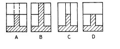
-
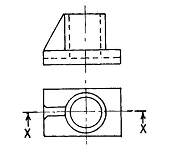
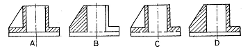
 Which of the following options below correctly shows the sectional view in the direction of arrow X – X?
-
 What is the name given to the type of section shown below? A. Part. B. Half. C. Removed. D. Full.
- Which of the following shows a part section?

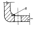
- In the figure below, X represents aA. Fillet. B. Spot face. C. Reccess. D. Chamfer.

THEORY
- Draw a diagram to illustrate a half section.
- Draw diagrams to illustrate part and full sections respectively.
WEEK EIGHT
OFFSET, BROKEN OUT AND REMOVED SECTIONS
CONTENT
(i) Offset, Broken-out and Removed.
OFFSET SECTION
The offset section is usually a full section. Unlike the full section earlier treated, the cutting plane changes direction at 900 from the main axis of the object to show details that are not in a straight line. More details are revealed by offset section than full section.

Offset section
BROKEN-OUT OR LOCAL SECTION
 When a small portion of an object is broken out in order to expose the interior details, such a partial section is called broken-out section. A free hand break line limits the sectioned area.
Broken-out section.
REMOVED SECTION
Another means of clarifying the shape of an object with a sectional view is to locate the sectional view away from the object. Such a section is called removed section. As a rule, the removed section should be labelled by letters such as section A-A or B-B as the case may be.

Removed section
EVALUATION
- Draw a suitable diagram to illustrate a broken-out section.
- With the aid of a suitable diagram, explain the following types of sections
(a) Off-set. (b) Removed.
READING ASSIGNMENT
Engineering drawing 1 by Parker and Pickup.Pages 78 – 93.
WEEKEND ASSIGNMENT
- What type of section is shown below? A. Revolved. B. Off-set. C. Part. D. Aligned.

- What type of section is shown in the figure below?
-
 Off-set. B. Removed. C. Broken-out. D. Part.
-
 What is the name given to the type of section shown below?
- Revolved. B. Removed. C. Broken-out. D. Half
-
 Which of the following shows correctly the section through the object shown below when viewed in the direction of arrow X?
- What type of section would . 4 depict having chosen your correct option?
A. Broken-out. B. Part.C. Removed. D. Off-set.
THEORY
- Draw a suitable diagram to illustrate an off-set section.
- Differentiate between removed and broken-out sections.
WEEK NINE
ALIGNED AND REVOLVED SECTIONS
CONTENT
Aligned and Revolved sections
ALIGNED SECTION
 When features are located so that the change in direction of the cutting plane is greater than 900 but less than 1800, the section view is drawn by revolving the angled part into a plane parallel with the line of sight of the sectional view. This type of view is called an aligned section.
Aligned section
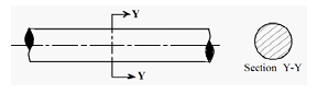
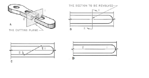
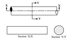
Revolved section
Revolved section are the actual local cross-sectional shape of an object such as frame work, rails, bars, arms or other elongated parts of an object. The cutting plane is assumed to have passed perpendicularly through the axis of the piece and then revolved through 900 in to the plane of the sheet containing the drawing


Revolved section
EVALUATION
- Draw a suitable diagram to illustrate an aligned section.
- Differentiate between revolved and aligned sections.
READING ASSIGNMENT
Engineering drawing 1 by Parker and Pickup.Pages 78 – 93.
WEEKEND ASSIGNMENT
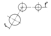
 What type of section is produced on plane P – P as shown below?
- Removed. B. Aligned. C. Part. D. Full.
- What is the name given to the type of section shown below?
 A. Aligned. B. Removed. C. Revolved. D. Part
Use the figure below to answer 3 and 4.

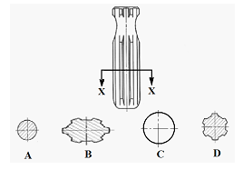
- What type of section is X – X? A. Half. B. Removed. C. Revolved. D. Aligned.
- How many different parts of the object are shown by the section?
A. Five. B. Four. C. Three. D. Two
- What type of section is suitable for showing the cross-section of a long bar?
A. Removed. B. Half.C. Revolved. D. Aligned.
THEORY
- With the aid of a suitable diagram, explain what you know about aligned section.
- Draw diagrams to explain the following types of sections
(a) Off-set. (b) Aligned. (c) Revolved. (d) Removed.
WEEK TEN
SECTIONAL VIEWS OF MACHINE PARTS
CONTENT
(i) Rules and examples of sectional views.
SECTIONING RULES
As a standing rule of sectioning, some machine parts must not be hatched when a cutting plane passes through them longitudinally (parallel to the axis of the part); order wise, they will lose their identity. These include solid shafts, bolts, nuts, studs, rivets, pins, spokes, balls and rollers of bearing, keys, screws, ribs and webs. It should be noted that if the cutting plane passes through them transversely (perpendicular to the axis of the part), they should be hatched. Note that hatching lines should be thin-continuous and its inclination should not be exaggerated. An angle of 450 is preferable.
 EXAMPLE 1
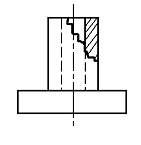
 Section through a web or rib
Note: Smaller cross sections of webs should be hatched for clarity sake
 EXAMPLE 2
Section through setscrews

EXAMPLE 3
Section through rivets


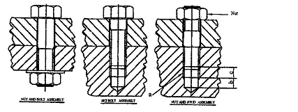
EXAMPLE 4
Section through nut, bolt, and stud assembly

EXAMPLE 5
Section through a Solid Shaft

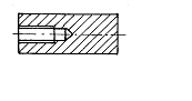
EXAMPLE 6
Section through a countersunk hole, blind hole and Counter bored hole.


EVALUATION
- State 6 machine parts that by rule should not be sectioned?
- With the aid of suitable diagram, explain a section through each of the following
(a) Countersunk. (b). Counter bore. (c) Blind hole
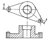
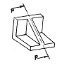
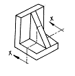
-
 The figure below is a pivot block. Draw its sectional view looking in the direction of arrow A.
Show all hidden details.
READING ASSIGNMENT
Engineering Drawing 1 by M.A.Parker and F.Pickup pages 172 – 179, 192 – 201
WEEKEND ASSIGNMENT


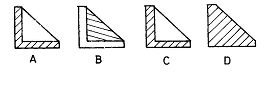
-
 Which of the following views represents section P-P as shown in the figure above?
- The section shown in the figure above is a
 A. tapped hole. B. reamed hole. C. drilled hole. D. countersunk hole.
- The section shown in the figure above is a
A. tapped hole. B. countersunk hole. C. drilled hole. D. counterbored hole.


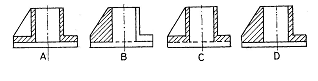
-
 Which of the following views represents section X-X as shown in the figure above?
-
 The figure below shows a casting. Which of the options that follows represents section X-X ?

 THEORY
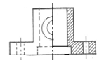
- The diagram above is a fulcrum support. Draw full size the sectional view on X-X
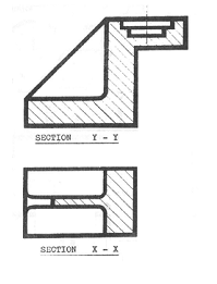
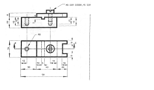
 The figure shown below is a machine part represented in first angle orthographic projection. Draw the
(i) Sectional view on X-X.
(ii) Sectional view on Y-Y


 They can be identified by the flatness of the ends which makes it possible to conveniently fit into theparts. They are used as shock absorbers in vehicles.