
Share this:
FIRST TERM E-LEARNING NOTE
SUBJECT: TECHNICAL DRAWING CLASS:SS1
SCHEME OF WORK
WEEK 1: Introduction to Technical Drawing. Types of Drawing and Applications
WEEK 2 Safe Working Habits.Instruments, Equipments and Materials.Care of Equipments.
WEEK 3 Board Practice.Title Block and Border Line
WEEK 4 Types of Line and their Uses.
WEEK 5: Lettering :Types and Styles of Lettering.
WEEK 6: Plane Geometry: Division of Lines into a Given Number of Equal Parts or Proportions
and their Applications.
WEEK 7: Circles.
WEEK 8: Angles.
WEEK 9: Triangles.
WEEK 10: Quadrilaterals.
WEEK 11.Revision and Examination.
Reference materials:
- Technical Drawing by J.N. Green.
- Engineering Drawing 1 by M.A.Parker and F.Pickup
- Metal Work Technology by G.H. Thomas.
- Drafting Technology and Practice by William P. Spence
- Technical Drawing by F.B Mayock ( 1- 4 )
- Basic Technology forJunior Secondary Schools book 1 by G.N Nneji, E.J. Okon, V.C. Nwachukwu, N.A. David, and T.C. Ogbuanya. Pages 1-17, 34-78.
- Basic Technology for Junior Secondary Schools book 2 by I. Elekwa , O.A. Bamiro, A.O. Oluyide,
- D.L Ladoye, A. Nurudeen and I.O. Akuru
- Technical Drawing for Senior Secondary Schools by Y.A Thanni and C.A Faseun-Motesho Pages 97-103
WEEK ONE
Introduction to Technical DrawingTypes of drawing and applications
![]() Content
Content
(i) Meaning and Importance of Technical Drawing.
(ii) Types of Drawing andApplication.
Meaning and Importance of Technical Drawing
Technical drawing is the use of lines, symbols and notes tocommunicate the information needed to construct an object.
In other words, it is simply a shorthand “language” which describes precisely, by means of drawing, whatever has been manufactured or is intended for manufacture.
Importance of Technical Drawing
As a student, irrespective of your discipline, you need to have the essential knowledge of technical drawing in order to enhance your creative ability of doing things and thus makes you efficient in your chosen profession. The ability to read drawings is important for many jobs including some that does not involve making of drawings. For example, a building materials salesperson needs to be able to read drawings to find out what materials must be delivered to a job site. Persons responsible for production supervision in manufacturing plant needs the knowledge of technical drawing to work efficiently and proficiently. Engineers who build highways, bridges and buildings work with drawings. It may be surprising for you note that even policemen needs drawing sketches to describe the scene of an accident. Tailors draw sketches of the dress they intend to sew. Carpenters use drawings for their wood works. An office manager can quickly express how he likes the furniture in a room arranged if he has the knowledge of technical drawing. A geographer that draws maps and contours together with a pilot that interprets these drawings to fly an aircraft successfully to its destination needs a basic knowledge in technical drawing. See the figures below for better illustration.
 What professional courses can I study at the university/polytechnic? As a technical drawing student, there are many courses you can study. Prominent among these are Engineering{mechanical, civil, electrical, systems, structural etc.), Quantity surveying and Architecture to mention just a few.
Types of Drawing and application
(a) Planning Drawings
(b) Survey Drawings
(c) Architectural Drawings (preliminary sketch designs, design or presentation drawings, working
drawings, and measured drawings )
(d) Engineering Drawings (Pictorial – isometric or 3-dimensional drawing, oblique drawing,
perspective drawing, and axonometric drawing. andOrthographic– 2- dimensional drawing)
1. Planning Drawing: This is a drawing made to show existing topography, roads, population, etc. It also shows some proposed new roads and zonal areas, statutory scheme maps anddetailed new development layouts.
2. Survey Drawing: This is the type of drawing used to show buildings, boundaries, water, arable
lands, vegetation, roads, footpaths etc in a particular geographical location. Different colors are used
to differentiate features e.g. Buildings – light crimson or neutral tint, Arable lands– sepia or burnt
umber,
Water– Prussian blue which is darkest at the edge, Vegetation – dark green and Pastures – light
green. The true North must be clearly indicated on this type of drawing.
3. Architectural Drawing: Architectural drawing is classified into different types and these include-
preliminary sketch designs, design or presentation drawings, working drawings and measured
drawings.
- Preliminary Sketch Design-: This is the type of drawing made in freehand sketch during the
process of trying to work out the main design. The sketch may include roughly set-up plan and
elevation. The purpose of a sketch design is to arrive at a solution of major problems only and
should therefore be tentative in character.
- Design or Presentation Drawings-: Finished design drawings show a minimum ofconstructional details. Although the construction must be fully worked out before they can be properly completed. The drawings may be in orthographic, isometric, or perspective projection respectively, accurately drawn and effectively rendered.
- Working Drawings-: They are the drawings from which the actual construction work is carried out. They must therefore give all the graphical information necessary for constructional purposes andmust be accurately drawn in orthographic projection of plan, elevation and essential sections.
- Measured Drawings-: These scale drawings are made from carefully taken measurements of existingbuildings of historic interest and architectural merit as part of students training in design or for purposes of record keeping. It may illustrate a whole building or part of a building.
4. Engineering Drawing: This may either be in pictorial (3 – dimensional) form e.g. isometric,
oblique, perspective and axonometric drawing respectively or in orthographic (2- dimensional) form
represented in plan, elevation and sectional views.
Evaluation Questions
1. Define Technical drawing ?
2. Describe with the aid of a sketched diagram, the route from school to your house.
3. List four basic types of drawing.
4. Mention three types of architectural drawing.
5. State the uses of the following types of drawing. (a) working drawing (b)survey drawing?
6. Sketch the orthographic (front, rear andend )views and pictorial drawing of your house.
7. Imagine a local community and make a survey drawing of it, Showing the buildings, foot paths,
vegetation and other captivating features.
Reading Assignment
Drafting technology and practice by William P. Spence. Pages 27- 31
Visit goggle for types of drawing and applications
Download the survey plan of your state of residence.
Weekend Assignment
Objectives
1. The use of lines, symbols and notes to communicate the information needed to construct an object
is called A. Mechanical engineering. B. Introductory technology. C. Technical drawing.
D. Scale drawing.
2. The following career opportunities are available for a technical drawing student Except.
A. Quantity surveying. B. Mechanical engineering. C. Architecture D. Accounting
3. Which of the following types of engineering drawing is represented in plan, elevation and section?
A. Isometric. B. Oblique. C. Perspective. D. Orthographic.
4. As an Architect or a civil Engineer in your family, which of the following would you take as a first
step in building a family house that your father has consulted you for? A.Give an estimated cost of
thebuilding. B. Put down his ideas in a sketch form. C. Ask for the proposed site of the building.
D. Ask for some money to start-off the building project.
5. In survey drawing, which of the following colors is used to represent water? A. Dark blue. B. Light
Prussian blue C. Light green D. Dark green.
Theory
- Define technical drawing?Mention five career opportunities available to you as a technical drawing student.
- State four basic types of drawing and their applications.
WEEK TWO
Safety; Safe Working Habits. Uses and Care of Equipment
![]()
Content
(i) Causes of Accidents and Safe Working Habits at the Workshop
(ii) Types, uses and care of equipments
Causes of Accidents at the Workshop
Accident is an occurrence that inflicts undesirable damage on its victim which could either be human or property due to lack of strict adherence to workshop safety rules. This sorry state of health could be caused by the following bad habit sometimes exhibited at the workshop and this includes:
1. Lack of concentration on the job being done.
2. Lack of provision of safety devices e.g. boots, eye goggles, hand gloves etc.
3. Failure to use the safety devices provided.
4. Failure to follow laid down methods of handling facilities eg instruction manual.
5. Horse (careless) play.
6. Fatigue or tiredness.
7. Failure to use the right tool for the right job.
Safe Working Habits
1. It is important to use the right tool for the right job.
2. Worn-out tools should not be used. They could cause physical injury.
3. Tools should be returned to the tool box after use.
4. Machines should be put off when not in use.
5. Safety wears should be used while in the workshop.
6. Electrical devices should be put off at the end of the days work.
Evaluation Questions
1. State six causes of accident at the workshop.
2. State six safety habits at the workshop.
Drawing equipments: Their uses and Care
In engineering drawing, one needs to know the various drawing instruments, their uses and care. Some of the instruments used in engineering drawing include:
 (i) Tee Square
(ii) Set Square
(iii) Pencil
(iv) Eraser
(v) French Curves
(vi) Drawing board
Drawing Board: A drawing board, as the name implies, is a board specially made for drawing. Drawing boards are made in sizes to correspond with drawing paper sizes. The most common types for general use are: (a) Half imperial (23 x 16) inches (b) Imperial (32 x 23) inches (c) Double elephant
(42 x 29) inches (d) Antiquarian board (54 x 32) inches.
![]()

![]()


![]()
![]()
![]()
![]()
Care for Drawing Boards:
1. The surface should be protected from knocks and scratches
2. If left on the table, it should be covered with cloth.
3. If put against a wall, the working side should face inwards
4. It should not be exposed to heat or moisture
5. Drawing pins should not be stuck in unnecessarily. Masking tape should be used to attach
drawing papers on the Board instead of pins.
 Tee Square: They are described in shape by the name. They are used for drawing horizontal lines. Types of Tee Square include:
Half imperial (24 inches blade) (b) Imperial (31 inches blade)
(c) Double elephant (42 inches blade) (d) Antiquarian (54 inches blade)
![]()
Care for Tee Square:
1. They should not be left lying about in bridging positions or leaning against walls.
2. They should be hung on pegs or left flat.
3. It should not be used as a hammer to knock in drawing pins into boards.
4. Loose blades should be tightened with screw driver.
 Set Square:Setsquares are used for drawing vertical and inclined lines. They are triangles of celluloid about 1/16 inches and are of three kinds: (a) 45 degrees (b) 60/30 degrees (c) adjustable.
Care for Set Square:
1. It should not be used as a screw driver or as a hammer
2. Clean with soap and water since this does not harm the celluloid with which set squares are made.

![]()
Pencil: Ordinary drawing pencils are made of cedar wood with ‘lead’ of compressed clay and graphite and are about seven inches long. The hexagonal shape is more easily held in fingers. The type of pencil depends on the degree of hardness and softness ranging from 9H, the hardest to 6B the softest. There is also HB, F, H and B. HB pencil is good for engineering drawingbecause it can perform the dual function of producing faint and bold lines as required by the user.
Care of Pencil
The best way of sharpening a pencil is by using an ordinary pen knife this prevents breakage.
Eraser: Alterations, corrections and the removal of unwanted pencil lines are best made by rubbing with a soft white rubber. Erasers should be kept away from fuels
French Curves:French curves are drawing instruments used for irregular curved lines which cannot be made up of arcs. They are either made of wood or celluloid like set squares.

Care of French Curves:
1. It should not be used as a screw driver or as a hammer.
2. Clean with soap and water
Templates: These are designed pattern of letters or objects either made on plastics or metallic plates. They are used for creating letters and shapes of objects.
Care of Templates:
They should be carefully handled in order to ensure that the engraved letters and symbols are not dented. They should be kept away from fuel.
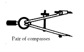 Pair of compasses: This type of drawing instrument is specially designed for drawing circles and arcs.
One leg terminates in a needle point and the other leg can be fitted with a pencil or pen.
Care of Compasses:
The needle point should not be blunt in order to avoid slippery and to maintain a smooth, even line for the curve.
 Pair of dividers: Dividers are designed in the same way like the compasses. The only difference is that the two legs end with needle points and also a spring screw attachment is on one of the legs for fine adjustments for some types of dividers. They are used for transferring distances.
Care of Dividers:
Ensure that the hinge is tight and the pin end should not be used as scribers in order to prevent bluntness.
 Protractor: This is either a semicircular or circular shaped object made of celluloid. It is calibrated in degrees. It is used to measure angles.
Care of Protractors
It should be properly kept in its box after use.
Ensure that it is not lying on the ground so that the calibration will not be cleaned. It can be washed with soap and water since this does not affect celluloid unlike fuels.
Drawing materials: Other materials used in the drawing room are: Clips, Pins, Masking tape and drawing sheet. The International organization sheet sizes are shown below.
A4 = 210 X 297
A3 = 297 X 420
A2 = 420 X 594
A1 = 594 X 841
A0 = 841 X 1189
Other types of equipment
Apart from board drawing instruments, there are other equipments used by engineers in the wood/metal workshop and these include:
1. Marking out tools.
2. Driving tools
3. Cutting tools.
4. Holding tools
5. Measuring tools.
6. Boring tools
Marking out tools: During fabrication in the workshop, object to be constructed is first measured, marked and cut out of the original one. The instrument used to mark this original sheet is calledamarking out tool. Examples of marking out tools include surface plate, scriber, pair of dividers, pair of compasses, odd-leg caliper, centre punch, tri-square, sliding bevel, trammel etc.
Driving tools: Engineering components that need to be tightly held together, require the use of one form of fastener or the other. The equipments used to achieve this aim are called driving tools. Examples of driving tools include Hammers, Screw drivers, Spanners, and Mallets.
Cutting tools: These are tools used in cutting metallic or wooden materials in the workshop. Examples include chisels, files, saws, planes, spoke shave, etc.
Measuring tools: A measuring tool as the name implies isan equipment used for measurement. Examples are steel rule, tape rule micrometer screw gauge, protractor,verniercalliper, outsidecalliper and inside caliper.
Holding tools: These are provisions and tools used to hold work pieces on the bench. Examples include bench vice, bench hook, lathe chuck, tongs, pliers, wrench and clamps
Boring tools: Brace with a drill bit, Gimlets and bradawls
Evaluation Questions
1. Mention ten types of drawing instruments and state the uses of each.
2. State six types of drawing instrument and how to care for each.
3. Draw the following instrument: T- square, French curve, a pair of compasses, pencil and a template.
4. Describe how the following tools can be used at the workshop (a) Scriber (b) Screw driver
(c) Chisel
5. Classify the following tools : Hammer, File, Chisel, A pair of dividers, Protractor, A pair of odd-leg
calipers, Vernier Caliper, Scriber, Saw, Centre punch, Screw driver, Surface plate, Spanner,
Steel rule, T- square, Tri-square into (i) Marking out tools (ii) Cutting tools (iii) Driving tools
(iv) Measuring tools.
6. State five types of drawing paper and their respective sizes.
Reading Assignment
Basic Technology for Junior Secondary Schools book 2 by I. Elekwa , O.A. Bamiro, A.O. Oluyide,
D.L Ladoye, A. Nurudeen and I.O. Akuru.Pages 75- 85.
Basic Technology for Junior Secondary Schools book 1 by G.N Nneji, E.J. Okon, V.C. Nwachukwu, N.A.
David, and T.C. Ogbuanya. Pages 1-17, 34-78.
Weekend Assignment
1. The type of instrument that can be used to draw the smallest circle is called A. circle template
B. Tee-square. C. Pair of compasses. D. pair of dividers.
2. Setsquares are used for drawing A. Set of squares. B. Curves. C. Vertical and inclined lines.
D. horizontal lines.
3. The best type of pencil used for drawing is A. 2B B. 6B. C. HB.D. 3H.
4. Which of the following drawing instruments is used for drawing symbols and letters? A Template.
B. Tee-square. C. Setsquare. D. Tri-square.
5. Which of the following instruments is best used for drawing horizontal lines? A. Tee-square.
B. Tri-square C. Ruler. D. Setsquare.
Theory
- (i) State five causes of accident in the workshop. (ii) State five safety habits that one could exhibit in order to prevent accident at the workshop.
- State six types of workshop tools and give three examples each.
WEEK THREE
Board practice
![]() Content:
Content:
(i) Introduction
(ii) Setting a drawing paper on the board.
(iii) Drawing of border line and title block
Introduction: A good drawing must not only be neat, it must be accurate. Neatness and accuracy can be achieved when the appropriate instruments are used in a proper way. It is worthy of note that good board practice is necessary for producing good drawings.
Board practice is therefore, the ability to effectively manipulate the use of drawing instruments and materials to produce a good drawing.
Setting a drawing paper on the board and other board practice
Procedures:
- Cut out four pieces of masking tape and place them at the top right hand corner of the board.
- Place the paper on the board.
- Set the left vertical edge to be about 25mm from the left edge of the board.
- Set the bottom edge of the paper to be at a convenient distance from the bottom edge of the board to allow for sufficient room to use the T-square at the bottom of the paper.
- Align the top edge of paper with the edge of the T-square.
- Hold down the paper with the right hand, move the T-square down with the left hand.
- Secure diagonally the four corners of the paper with a masking tape.


Note: Drawing instruments can be combined while drawing. For instance, the combination of a T-square and setsquare can be used to produce vertical and inclined lines.
Drawing of border lines
 A border line is a line drawn round the four edges of the drawing paper. It is drawn as soon as the drawing paper has been set on the drawing board.A Border line could be regarded as the frame of the drawing paper. It is given a margin of about 12mm or 15mm from the edges of the drawing paper. A title block is drawn inside the border line. The recommended line type used for drawing border lines isthick continuous.
Procedures:
- Measure 12mm from the four edges of the drawing paper already fixed to the board.
- With the aid of the T-square and set-square, draw vertical lines at 12mm from the left edge of the drawing paper. Repeat same at the right end of the paper.
- Using the T-square only, draw a horizontal line at the 12mm mark at the top and bottom ends of the paperto complete the border.
Drawing of title block
 Vital information about the part drawn by a draughtsman such as, title of the drawing, materials of which the part is made, the scale used for the drawing, date, name of the draughtsman, etc are as a convention carefully written down in a title box which in most cases is placed at the bottom right hand corner of the drawing sheet. Below is an example of title block for school use.
Evaluation Questions
- Draw title blocks for school use on a plane paper.
- Draw a border line on a plane paper.
- Draw five vertical lines spaced at a distance of 20mm from each other. Repeat the exercise with five horizontal lines.
- Draw a vertical line. Step out six equal distances on it. Then draw lines inclined at angle 600 on each point using a t-square combined with a setsquare.
- Engineering drawing by M.A Parker book 1, page 8 questions 1, 2 and 3. Draw on plane paper.
Reading assignment
- Basic technology for junior secondary schools book 1 pages 43-47
- Visit the internet to get more information about title blocks and board practices
Weekend Assignment
1. What combination of instruments is best used for drawing vertical lines? A. T-square and setsquare.
B. Protractor and dividers. C. Ruler and pencil. D. Set-square and tri-square.
2. Which part of a drawing page is the title block located? A. Top right corner. B. Bottom right
corner. C. Top left corner. D. Bottom left corner.
3 The type of line used for drawing a border line is A. thin continuous. B. thick continuous.
C. short dashes.D. thick continuous chain.
4. Border lines are drawn at what distance from the edge of the drawing paper? A. 14mm. B. 25mm.
C. 12mm. D. 30mm.
5. The drawing instrument which is used in drawing shapes is called A. stencil. B. template. C. French
curve. D. pair of compasses.
Theory
- Draw a neat title block for school use.
- Draw a vertical line. Step out six equal distances on it. Then draw lines at each point inclined at angle 600 to the left and to the right using a t-square combined with a setsquare..
WEEK FOUR
Types of line and their uses
![]() Content:
Content:
(i) Types of line and their uses
Types of lines
Thick continuous line: This is a thick and solid line used to show visible outlines of an Object.
They are also used as border lines (15mm from paper margin).
![]()
Thin continuous line: This is a thin and solid line used for dimension lines, lines, projection lines, leader lines, hatching or section lines etc.
![]()
Short dashes: The dashes are about 3mm long and spaced about 1mm from each other. These are approximate values and will depend on how large the drawing might be. They are used to represent hidden details.
![]()
Thin continuous chain line: These are thin lines made of long and short dashes. The long dashes can be about 19-38mm long while the short dashes may be about 1.5mm long. The length will vary with the size of the drawing and the length of centre line needed. They are used for centre lines
![]()
![]()
![]() Thick continuous chain with arrow head: They are thick lines made of either long and short dashes or equal sized dashes. Arrow heads are drawn on their ends to show the direction in which the section was taken. They are used for cutting and viewing planes.
Thick continuous chain with arrow head: They are thick lines made of either long and short dashes or equal sized dashes. Arrow heads are drawn on their ends to show the direction in which the section was taken. They are used for cutting and viewing planes.
![]()
Thick irregular solid lines: These are thick solid lines drawn freehand. They are either short break or long break lines used to show the part of an object that has been removed. The long break lines are drawn as thin solid lines with Z symbol inserted in several places along its length.
![]()
![]()
![]()
![]()
![]()
![]()
![]()
![]()
![]() or
or
![]()
![]() Continuous irregular wavy lines: They are thin lines drawn freehand and are used to indicate the limit of partial views.
Continuous irregular wavy lines: They are thin lines drawn freehand and are used to indicate the limit of partial views.
Phantom lines: These are tin dashes lines drawn with one long dash followed by two short dashes. They are used to show alternate positions of moving parts. The original position is drawn with visible
(thin continuous) lines while its rotated or new position is shown with phantom lines.
![]()
Evaluation Questions
1. List 7 types of line?
2. Sketch the following types of line and state their uses? (i) Continuous irregular wavy line. (ii) Thin
continuous chain. (iii) Thick continuous chain. (iv) Short dashes.
Reading assignment
- Drafting technology and practice by William P. Spence. Page 51 – 53.( school library)
- Visit the internet to get more information about lines.
Weekend Assignment
1. What type of line is used to show limit of partial view? A. Phantom. B. Thick irregular solid line.
C. Continuous irregular wavy line. D. Thick continuous line.
2. What type of line is used for hidden details? A. Thin long chain. B. Thick long chain. C. Short
dashes. D. Phantom.
3. Centre lines are drawn with what type of line ?A. Short dashes. B. Thin long chain. C. Continuous
wavy. D. Thick continuous chain.
4. What type of line is used to show visible edges or outlines? A. Thin continuous solid. B. Thick
continuous solid. C. Thick irregular solid. D. Short dashes.
5. The following are examples of line types except. A. quantum. B. phantom.C. short dashes .
D. thin long chain.
Theory
1. State 7 types of line and their uses
2. Draw the following types of line: (i) Phantom (ii) Continuous irregular wavy (iii) Short dashes.
WEEK FIVE
Lettering
![]() Content:
Content:
(i) Definition, types and style.
Definition: Lettering involves the process of putting down legible and neat information in drawings. Such pieces of information may either be in the title block or short statements written as titles of sectional views.
Types and Styles of Lettering
 Single line lettering: This is used in labeling, dimensioning and putting notes on drawings. A single line alphabet is required. In order to illustrate the shape and proportions, guide-lines are drawn to divide the height of the letter into eight equal parts and the centers of arcs are indicated. The lettering should however be drawn free hand at various sizes such as 1 inch, Half inch, one-quarter inch and one-eight inch high. See examples below.
 Inclined lettering: The inclined lettering is similar to the single-line lettering in all respect except for its inclined or uniform sloping of letters at an angle of about 750. The slope should not be exaggerated. See examples below.
 Script lettering: This could be written with pencil or with ordinary freehand pen. See examples below.
 Stenciled lettering: This is used for the titling of architectural and other drawings especially where numbers of drawings all have the same title. See examples below.
 “Uno” pen lettering:These letters are produced with the special “Uno” pens and guides. They are extensively used for drawings of all kinds particularly working drawings and details. Its popularity is due to its legibility, speed of execution and the uniformity which it gives. See examples below.
Gothic lettering:For whosoever shall call upon the name of the Lord shall be saved.
1 2 3 4 5 6 7 8 9 10 11 12 13 14 15 16 17 18 19 20
Evaluation Questions
1. Using Script lettering, write the 26 alphabets and 20 figure both in uppercase and lowercase.
2. Using Gothic lettering, write the following: If any student be in Christ Jesus, he is a new
creature. Old life of sin will give way for a new life of righteousness.
Weekend Assignment
- (i) Using inclined lettering style, write the school vision. (ii) At what angle is inclined lettering done?.
- Using script lettering, write ten top goals you want to achieve in life.
WEEK SIX
Plane geometry
![]() Content:
Content:
(i) Division of a straight line into equal number of parts.
(ii) Division of a straight line into a given proportion.
(iii) Applications of division of lines.
Straight line: A straight line could be defined as a distance between two points. In other words, it is the locus of a point equidistant from two fixed points.
Division of a straight line into a number of equal parts
Example 1: Divide a straight line 120mm into two equal parts.
Method:
(i) Draw a straight line AB equal to the given length ie 120mm.
(ii) With compass pin at point A and radius equal to three quarter of the given line, draw arcs above and
below the straight line.
(iii) With compass pin at point B and same radius as in (ii), draw arcs to cut the former ones.
(iv) The straight line joining these points of intersection P and Q bisects line AB into two equal parts.
 This line is called a bisector or perpendicular bisector
Example 2: Divide a straight line 100mm in 8 equal parts.
Method:
(i) Draw a straight line AB equal to the given length ie100mm.
(ii) Draw another straight line at an acute angle to the first line ieAC.
(iii) Use a pair of compasses or dividers to mark out 8 equal divisions on line AC.
(iv) Join the eighth division to point B.
(v) Using the combination of a setsquare and ruler, draw lines from each of the remaining 7
 divisions parallel to the line B C.
Example 3: Find by construction, the square root of a straight line 63mm long.
Method:
 (i) Draw the given straight line equal to 63mm.
(ii) The highest perfect square in 63mm is 49mm which is(7×7).
(iii) Therefore, divide the given straight line into 7 equal parts.
(iv) One-seventh of this given line is the required square root.
Evaluation Questions
1. Draw a line 75mm and divide it into 4 equal parts.
2. Find the square root of a line 125mm in length.
Division of a straight line into a given proportion
Example 4: Divide a straight line 120mm in the ratio of 2:1:4
Method:
(i) Draw the given straight line AB equal to 120mm.
(ii) Add the ratios together ie 2+1+4 =7.
(iii) Draw another line AC at an acute angle to line AB.
(iv) Use a pair of compasses or dividers to mark out 7 equal divisions on line AC.
(v) Join the seventh division to point B.
(vi) Using a setsquare and ruler, draw lines parallel to line AC at point 3 and 2 which are the third and
second divisions respectively.

Applications of division of lines
 The division of line into a given number of parts or proportions is applicable in the enlargement and reduction of figures See an example below. It can also be used to determine the square root of a straight line as shown above.
Fig. Frame ABCD reduced in the proportion 3:5 to A1B1C1D1
Method:
(i) Draw the given rectangle ABCD.
(ii) Mark a point P at a convenient distance to the drawn rectangle.
(iii) Radiate lines from point P to the four corners of rectangle ABCD.
(iv) Since we are to draw a reduced figure, it means that from the given proportion (3:5), the actual size is
5 while the reduced size is 3. Therefore, divide line PA into 5 equal parts.
(v) At the third (3) part, draw a line A1D1 parallel to AD.
(vi) Repeat same for the remaining sides to obtain the required reduced rectangle A1B1C1D1.
Evaluation Questions
1. Draw the bisector of a straight line 70mm long.
2. Divide a line 105mm into 7 equal parts.
3. Divide a line 96mm in the proportion 2:3:2
4. Find by construction the square root of a straight line 122.5mm long.
Reading Assignment
Technical drawing for school certificate and G.C.E by J.N Green Page 11-13.
Weekend Assignment
1. A line that divides a straight line into two equal parts is called. A. perpendicular bisector.B. locus.
C. perpendicular line. D. angular bisector.
2. The locus of points equidistance from two points is a A. circle. B. straight line. C. arc. D. angle.
3. In dividing a straight line AB into a number of equal parts, the first step is to A. divide line AB
using a ruler. B. draw a line at an acute angle to the given line AB. C. use a pair of dividers to
divide line AB. D. use a pair of compasses to divide line AB.
4. A line to be divided in the ratio of 2:4:3:1 will have a total number of how many equal divisions?
A. 8. B. 10. C. 6 D. 4.
5. The square root of a straight line 90mm is ———– of the given line. A. one-eight. B. one- sixth.
C. one-ninth. D. one-tenth.
Theory
1. Divide a line 105mm into 7 equal parts.
2. Divide a line 96mm in the proportion 2:3:2
WEEK SEVEN
Circles and its Properties
![]() Content:
Content:
(i) The meaning and types of circle.
(ii) Properties and construction of a circle.
Meaning and Types of Circle
A circle is a plane figure bounded by a closed curved line called circumference which encloses an angle of 3600 at its centre. In other words, a circle could be defined as the locus of point equidistance from a fixed point. Circles could either be arranged in a concentric or eccentric form respectively. While concentric circles have same center but different radii, eccentric circles have different centers and radii. The space between two concentric circles is called annular.

![]()
Properties and construction of a circle.

Diameter: A diameter is a straight line that connects two points of a circle via the centre.
Radius: A radius is a straight line drawn from the center to the circumference.
Arc: An arc is any length along the circumference.
Chord:A chord is a straight line that connects a circle in two points via an area other than the centre.
Tangent:A tangent is a line drawn to just touch the circumference of a circle and always at right angle to the radius of the circle.
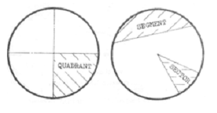
Segment: This is the part of a circle bounded by an arc and a chord.
Sector: This is the part of a circle bounded by an arc and two radii.
Secant: This is a straight line that intersects a curve at two or more points.
Quadrant: A quadrant is part of a circle bounded by two radii inclined at 900 and an arc.
Annular: This is the space between two concentric circles.
Circumference: This is a smooth curved line traced out by a point which moves round a fixed center and is always at equal distance from it.
Construction
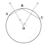
To determine the centre of a circle.
Method:
(i) Draw any two chords AB and AC on the circle.
(ii) Draw the bisectors of AB and AC. These bisectors meet at a point representing the required centre of
the circle.
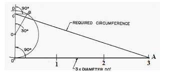 To find graphically the circumference of a circle.
Method:
(i) Draw a semi-circle with diameter DD1 equal to the diameter of the given circle.
(ii) Draw a line D1A at right angle to the diameter D1D.
(iii)Mark-off on the line D1A diameter D1D in three places to get points 1, 2 and 3.
(iv) From the centre O, draw a line OB at 300 to OD.
(v) From point B, draw BC at right angle to OD.
(vi) Join C to point 3. C-3 is the required circumference.
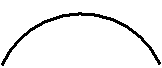
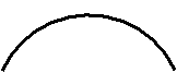
 To draw a straight line of approximate length to a given arc.
Method:
(i) Draw the given arc AB.
(ii) Connect the two ends of the arc ie A and B with a straight line and extend to C with length BC equal tohalf AB.
(iii) Join point A and B to the centre of the arc O.
(iv) With C as center and radius CA, draw an arc.
(v) Draw a line at 900 to OB from B to meet the previous arc at point D. DB is the required straight line.
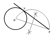 To construct a tangent to a circle from a given point outside it.
Method:
(i) Draw the given circle with centre O.
(ii) Locate the given point P.
(iii)Draw a line to connect the given point P to the centre of the given circle.
(iv)Construct a semicircle on OP and this cuts the given circle at point N.
(v) Connect a line from P through N. This is the required tangent.
Evaluation Questions
 1. Choose any convenient point S and draw a tangent to the circle shown below.
2. Determine graphically the circumference of a circle, diameter 35mm.
3. Construct a line of approximate length to the given arc shown below.
4. State 6 properties of a circle and explain each.
Reading assignment
Technical drawing by JN Green.Pages 18-21, 24.
Weekend Assignment
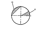 Use the figure below to answer question 1 and 2
1. The portion labeled P in the figure is aA. sector. B. segment. C. section. D. quadrant.
2. The portion marked Q in the figure is aA. quadrant. B. secant. C. segment. D. chord.
3. In the figure below, the line OS is aA. tangent. B. normal. C. secant. D. chord.
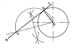
4. What type of polygon can be constructed with K as the centre in the figure below? A. Square.
B. Pentagon. C. Hexagon. D. Heptagon.

5. If the line PQ in the figure below is produced to G, the line PG obtained is a A. diameter. B. chord.
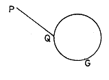 C. normal. D. secant
Theory
1. Determine graphically the circumference of a circle, diameter 35mm.
2. Construct a line of approximate length to the given arc radius 3mm shown below.
WEEK EIGHT
Angles
![]() Content:
Content:
(i) Meaning and types of angles.
(ii) Construction of angles ![]()
Meaning and Types of Angles
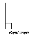 The point where two straight lines meet is called an angle. Its unit of measurement is degrees. Angle is of different types depending on the inclination of these two straight lines. If the two straight lines are inclined at an angle of 900, it is called a Right angle. If the angle of inclination of the two straight lines is less than 900, it is called an acute angle. If it is greater than 900 but less than 1800, it is called an Obtuse angle. If it is greater than 1800 but less than 3600, it is called a reflex angle. See the diagrams below for more illustrations.

Evaluation Questions
1. Define an angle.
2. Explain with the aid of suitable diagrams, 4 types of angle.
Construction of Angles
Angles are constructed using a pair of compasses, ruler and a pencil. However, they are measured with a protractor. Angles such as 900, 450, 300 and 150 are respectively obtained by the bisection of 1800, 900, 600 and 300. Before we consider the construction of these angles, we must first consider the bisection of an angle.
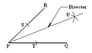 To bisect an angle.
Method:
(i) Draw the given angle QPR as shown above.
(ii) With P as centre and any convenient radius, swing an arc to cut line PR and PQ respectively at
points S and T.
(iii) With S and T as centers respectively swing arcs to intersect at point U.
(iv) Join PU.
To construct angle 900( bisect angle 1800 )
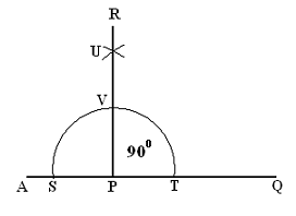
Method:
(i) Draw a line AQ of any convenient length for this purpose.
(ii) Choose a point P. With P as center and any convenient radius
PT or ST, draw an angle of 1800ie arc SVT. Bisect this angle
as follows:
(iii) With S as center and any convenient radius, swing an arc. With
T as center and same radius, swing another arc to intersect the
first one at point U.
(iv) Join line PR. Therefore < QPR = < APR = 900
To construct angle 450( bisect angle 900 )
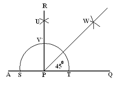
Method:
(i) Construct angle 900 as shown above and bisect it
as follows:
(ii) With V and T as centers in turn, and any
convenient radius, swing arcs to intersect at point W.
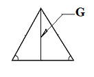
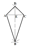
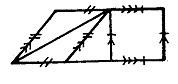
(iii) Join PW, the angular bisector. Therefore, Method: (i) Draw a line AQ and mark point P anywhere on it. (ii) With P as center and any convenient radius PT or PS, draw a semi circle(angle 1800). (iii) With T as center and same radius, swing an arc to cut thesemi circle at point V. (iv) Draw a line from P through V. To construct angle 300( bisect angle 600 ) Method: (i) Construct an angle of 600 as shown above. (ii) Bisect the 600 angle (with V and T as centers in turn and any convenient radius, swing arcs to intersect at point W). (iii) Join PW. Therefore, Summary 1. To construct angle 1800, bisect angle 3600 (circle). 2. To construct angle 900, bisect angle 1800. 3. To construct angle 450, bisect angle 900. 4. To construct angle 600, divide a semi circle into three equal parts. A third part of these divisions is 600. 5. To construct angle 300, bisect angle 600. 6. To construct angle 150, bisect angle 300. 7. To construct angle 750, construct (600 + 150). 8. To construct angle 1050, construct (900 + 150) Evaluation Questions 1. Construct the following angles (i) 150 (ii) 750 (iii) 1050(iv) 1200 (v) 1500 2. Define an angular bisector. Reading assignment Technical drawing for school certificate and G.C.E by J.N Green Page 11-16 Weekend Assignment 1. A circle has a total of how many degrees? A. 1800 B. 3600 C. 900 D. 600 2. Which of the following is the right instrument for constructing angles? A. Protractor. B. A pair of compasses. C. A pair of dividers. D. Setsquare. 3. Which of the following instruments is best used for measurement of angles? A. Protractor. B. A pair of compasses. C. A pair of dividers. D. Measuring rule. 4. In order to construct angle 150, which of the following angles is bisected? A. 1500 B. 600 C. 300. D. 450. 5. Which of the following angles is greater than 1800 but less than 3600? A. Obtuse. B. Acute. C. Reflex. D. Right angle. Theory 1. Construct the following angles (i) 150 (ii) 750 (iii) 1050(iv) 1200 (v) 1500 2. Explain with the aid of suitable diagrams, 4 types of angle. WEEK NINE Triangles (i) Meaning and types of triangle. (ii) Construction of triangles Triangles are plane shapes bounded by three straight lines. There are different types of triangle and these include: (i) Right angled triangle one of its angles equals 900 (ii) Isosceles triangle two equal straight lines meet to form one vertical angle and also form two equal base angles with the third side. (iii) Equilateral triangle all three sides and angles are equal Method: (i) Draw a line AB equal to the given length. (ii) With A as centre and radius AC, draw an arc. (iii) With B as centre and radius BC, draw an arc to intersect the previous arc at C. (iv) Join A and B to C. ABC is the required triangle. To construct a triangle when given two sides and one angle. Method: (i) Draw AB equal in length to one of the given sides. (ii) If the given angle is at point B for instance, then construct an angle (iii) With A as centre and radius AC equal to the length of the second side, draw an arc to cut BD at point C. ABC is the required triangle. To construct a triangle when given the altitude and two base angle (i) Draw a line PQ of any convenient length. (ii) Draw another line MN at a distance equal to the given altitude and parallel to line PQ. (iii) Construct the given base angle at S. Join SR which cut line MN at T. (iv) Join TU such that < TUS is equal to the second base angle. STU is the required triangle. Method: (i) Draw a line AB of length equal to the given hypotenuse. (ii) Bisect the hypotenuse AB to get a mid point D. (iii) With D as centre and radius DA or DB, draw a semi circle on line AB. (iv) Construct the given angle. Join AE which cuts the semi circle at C. (v) Join CB. ACB is the required triangle. To construct a triangle when given the base, altitude and vertical angle. (i) Draw the base line AB. (ii) With your protractor at A, draw given vertical angle Ө. (iii) Construct a perpendicular AD to line AC at A. (iv) Bisect line AB whose bisector cuts AD at P. (v) With P as centre and radius PA, draw a circle. (vi) Draw LM parallel to AB at a distance equal to the given altitude to cut the circle at F. (vii) Join AF and FB. AFB is the required triangle. To construct an isosceles triangle when given the perimeter and vertical height. Method: (ii) Bisect line AB to get the mid point C. (iii) Erect a perpendicular CD at C of length equal to the vertical height. (iv) Join DA and DB. (v) Draw DE such that (vi) Draw DF such that (vi) Triangle EDF is Isosceles. To construct a triangle when given the base, a base angle and the perimeter. (i) Draw a line AB equal in length to the given base. (ii) Construct the given angle at A and mark off AC equal to “perimeter-base”. (iii) Join C to point B (iv) Bisect line CB whose bisector cuts line AC at D. (v) Join DB. (vii)ADB is the required triangle. To construct a triangle when given the altitude, perimeter and vertical angle. (i) Draw line AB and AC such that given vertical angle. (ii) Mark off AD and AE equal tohalf the given perimeter respectively. (iii) Erect perpendiculars at points D and E to intersect at point F. (iv) With F as centre and radius FD or FE, draw an arc. (v) With A as centre and radius equal to the given altitude, draw a second arc to cut AB at point G. (vi) Draw a common tangent to the two arcs to cut AB at G and AC at H. (vii)AGH is the required triangle. To construct a triangle when given the perimeter and sides in a given ratio Method: (i) Draw a line AB of length equal to the given perimeter. (ii) Divide line AB into the given ratio by proportional division.i.e. 2:3:4 ( 2+3+4 = 9 ) (iii) Draw a line at an acute angle to AB and divide it into 9 equal parts. Join the last division to B. Then draw lines in the proportion 2:3:4. at C and D as shown above. (iv) With C as centre and radius CA, draw an arc. (v) With D as centre and radius DB, draw a second arc to cut the first one at E. (vi) Join EC and ED. Therefore, CDE is the required triangle. Method: (i) Draw the given triangle ABC and extend the base AC to both sides. (ii) With A as centre and radius AB, draw an arc to cut CA produced at D. (iii) With C as centre and radius CB, draw an arc to cut AC produced at E. (iv) Draw DF equal to the perimeter of the required triangle at any convenient acute angle to line DE. (v) Join FE and draw GC and HA parallel to FE. (vi) With H as centre and radius HD, draw an arc. With G ascentre and radius GF, draw another arc to intersect the previous arc at J (vii) Join JG and JH . JGH is the required triangle. Evaluation Questions 1. A triangle has a perimeter 130mm, base 40mm and a base angle 1050. (i) Construct the triangle. (ii) Measure and state the other base angle. (WAEC) 2. Construct a triangle PQR with base = 70mm, vertical height = 50mm and vertical angle = 550 . (WAEC) 3. Construct a triangle ABC in which pass through the three given points A, B, and C and then construct a tangent at point B. Measure the radius ofthe circle.(WAEC) 4. Construct a triangle whose perimeter is 120mm and of sides in the ratio 3:4:5. (WAEC). 5. Construct a triangle of sides AB = 60mm, AC = 55mm and < ABC = 600. Construct a triangle similar to this and whose perimeter is 140mm. 6. A metallic square pipe of length 120m is required by three boys to construct a triangle whose sides are proportional to the respective height of each boy. If each boy should cut a length equivalent to his height which are in the proportion of 3:4:6, determine (a) the size of each angle of the triangle. (b) thelength cut by the tallest boy. 7. Draw an equilateral triangle ABC of side 70mm, making AB the base. Through the vertex C, draw CD parallel to AB on the right hand side. Join BD and answer these questions: (a) what is the length of BD?(b) what name can you call figure ABDC? (c) what is BC called as it relates to BCD? (d) what is the value of angle BDC? 8. Construct an isosceles triangle, given a vertical height of 60mm and vertical angle of 450, 221/2 0 on each side. State the length of the base and one side. 9. Construct a triangle whose three sides are in the ratio 4: 5:7 and its perimeter 120mm. Reading Assignment Technical drawing by JN Green. Pages 64-67 Weekend Assignment 1. The isosceles triangle shown above requires two parameters for its construction. These include its perimeter and A. base angle. B. vertical angle. C. vertical height. D. hypotenuse. 2. Which of the following types of triangles has all its sides and angles equal.A. isosceles. B. scalene. C. equilateral. D. right angle. 3. The part labeled G in the triangle shown above is called A. median. B. hypotenuse. C. altitude. D. height. 4. A triangle which has unequal sides and angles is called A. oblique. B. scalene. C. equilateral. D. isosceles. C. peak. D. Angle. Theory 1. Construct a triangle PQR with base = 70mm, vertical height = 50mm and vertical angle = 550. 2. Construct a triangle ABC in which passthrough the three given points A, B, and C and then construct a tangent at point B. Measure the radius ofthe circle.(WAEC). WEEK TEN Quadrilaterals (i) Meaning and types of quadrilateral. (ii) Construction of quadrilaterals. Meaning and Types of Quadrilateral These are plane shapes bounded by four straight lines. The sum of angles in a quadrilateral is equal to 3600. Examples are as follows: Square: This is a quadrilateral with all sides equal; all angles 900, diagonals are equal and bisect each other at right angle. Rectangle: This is a quadrilateral with opposite sides equal, all angles 900, diagonals are equal and bisect each other but not at right angle. Rhombus: This is quadrilateral with all sides equal, opposite angles other than 900 equal and diagonals bisect each other at right angle. Rhomboid (parallelogram): This is a quadrilateral with opposite sides equal, opposite angles equal and diagonals bisect each other. Trapezium: This is a quadrilateral with only two opposite sides parallel. Diagonals does not bisect each other. Trapezoid: This is a quadrilateral with all sides and all angles unequal. Diagonals does not bisect each other. Deltoid (Kite): This is a quadrilateral with two pairs of adjacent sides equal; diagonals bisect each other at right angle and only one diagonal is bisected. Below are diagrams to illustrate the different types of quadrilateral. Evaluation Questions 1. What are quadrilaterals? 2. Explain the following types of quadrilaterals (i) trapezoid. (ii) deltoid. (iii) rhomboid. 3. Draw the following types of quadrilaterals (i) trapezium. (ii) rhombus Construction of Quadrilaterals To construct a square when given the length of side Method: (i) Draw the given side of length AB (ii) Construct a right angle at A. (iii) With A as centre and radius AB, draw an arc to cut the perpendicular from A at point D. (vi) With B and D as centers in turn and radius AB, draw arcs to intersect at C. (v) Join DC and CB. To construct a square when given the length of one diagonal. Method: (i) Draw the given diagonal AC. (ii) Bisect AC to get the mid point E. (iii)With E as centre and radius EC or EA, swing an arc to cut the bisector of AC at D and B respectively. (iv)Join AD, DC, CB, and BA to complete the square Method: (i) Draw one side AB. (ii) Construct a right angle at A. (iii)With A as centre and radius equal to the length of the second side, swing an arc to cut the perpendicular at A at point D. (v) Join DC and CB to complete the rectangle. To construct a rectangle when given the length of the diagonal and one side. Method: (i) Draw the given diagonal AC. (ii) Bisect to get the mid point E. (iii)With E as centre and radius EC or EA, draw a circle on AC. (iv) With A as centre and radius equal to the given side, swing an arc to cut the circle at D. (v) With C as centre, and radius equal to the given side, swing another arc to cut the circle at B. (vi) Join AD, DC, CB and AB to get the required rectangle. Method: (i) Draw AC equal in length to the given diagonal. (ii) With A and C in turn as centres and radius equal to the given side, swing arcs above and below line AC to intersect at points D and B respectively. (iii)Join AD, DC, CB and AB to complete the rhombus. Method: (i) Draw one side AB. (ii) Construct the given angle at point B or as the case may be. (iii)With B as centre if angle B is given and radius equal to the second side, swing an arc to cut BE at C. (vi) With A as centre and radius equal to second side, swing another arc to intersect the previous one at D. Join AD and DC. Method: (i) Draw one of the given parallel sides AB. (ii) Construct the given angle at A or as the case may be. (iii) Construct a parallel line FG at a distance equal to the perpendicular distance. This line cuts AE at D. (iv) With D as centre and radius equal to the length of the second parallel side, swing an arc to cut FG at C. (v) Join CB to complete the trapezium. Method: (i) Draw the longest diagonal BD and mark off the point of intersection E on it. (ii) Draw the shortest diagonal AC through point E with AE equals EC. (iii) Join AB, BC, CD and DA to complete the deltoid. Evaluation Questions 1. Construct a square of sides 45mm long. 2. The length of the diagonal AC of square ABCD is 70mm. Construct the square and determine the length of its side. 3. ABCD is a rectangle. Diagonal AC is 80mm long while length AB is 65mm. Construct the rectangle. How long is the width of the rectangle? Reading Assignment Technical drawing by JN Green. Pages 25-28 Weekend Assignment 1. A quadrilateral with unequal sides and unequal angles is a A. deltoid. B. rhombus. C. square. D. trapezoid. C. Trapezium. D. Rectangle. D. rectangle. 5. How many lines of symmetry has a deltoid? A. Two. B. One. C. Three. D. Four. Theory 1. The length of the diagonal AC of square ABCD is 70mm. Construct the square and determine the length of its side. 2. ABCD is a rectangle. Diagonal AC is 80mm long while length AB is 65mm. Construct the rectangle. How long is the width of the rectangle To construct angle 600( one – third of angle 1800 )
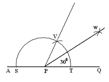
![]() Content:
Content:![]()
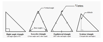 (iv) Scalene triangle all three sides and angles are unequal.
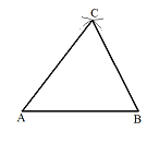 To construct a triangle when given the length of three sides.
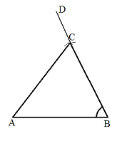
 Method:
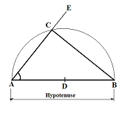 To construct a triangle when given the hypotenuse and an included angle.
 Method:
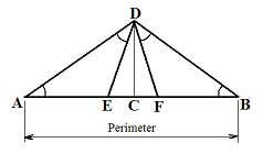 (i) Draw a line AB equal to the given perimeter.
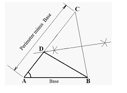 Method:
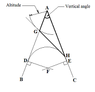 Method:
 (for instance 2:3:4)
 To construct a triangle similar to a given triangle but with a different perimeter.
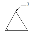 5. What is the name given to the part labeled J in the triangle shown below? A. Point. B. Vertex.
![]() Content:
Content:![]()
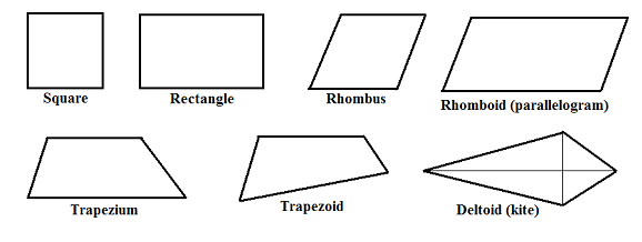
 4. List 7 types of quadrilaterals known to you and draw the diagram of each.
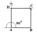
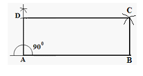 To construct a rectangle when given the length of two sides.
 (iv) With D as centre and radius AB, swing an arc and with B as centre and radius AD, swing another arc to intersect the previous arc at point C.
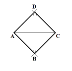 To construct a rhombus when given the length of the diagonal and one side.
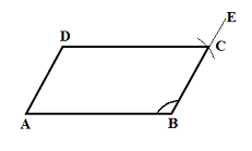 To construct a rhomboid when given the length of two sides and one angle
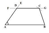 To construct a trapezium when given the length of the parallel sides , the perpendicular distance between them and one included angle.
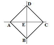
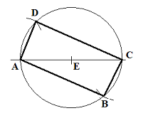
 To construct a deltoid when given the length of the diagonals and their point of intersection.
 2. Which of the following plane figures is not represented in the figure below? A. Square. B. Rhombus.
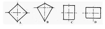 3. Which of the following quadrilaterals is a deltoid?
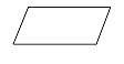 4. The quadrilateral shown below can be identified as a A. rhombus. B. rhomboid. C. deltoid.
Share this:


